Future Development Plan

Overview Main Image

Overview

Overview

The Future Development Plan builds upon the core strategies described in the Future Development Concept, including:

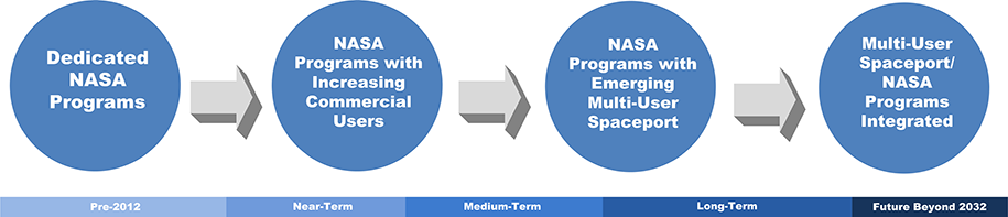
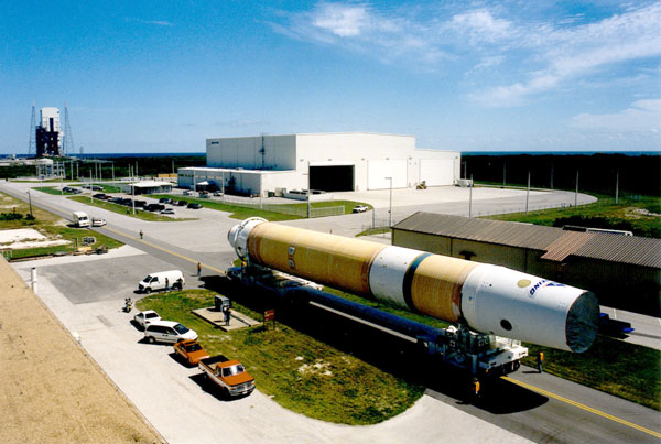
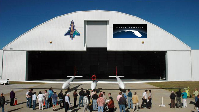
  • Evolution to a multi-user spaceport :Moving from a monolithic NASA program field installation to a multi-user spaceport on federal property. The evolution to a multi-user spaceport is not necessarily timeline dependent, but rather based on increased users and operators in line with space market demand.
  • Leaner and greener :Operational, fiscal and environmental sustainability.
  • Divest without diminishing :Divesting of assets without eliminating capability to serve both critical government missions and programs while encouraging the growth of commercial space transportation market needs.

Building on this strategic foundation, the Future Development Plan describes the stages that will facilitate KSC’s transformation to an economically sustainable multi-user spaceport. To support this transformation, the Future Development Plan outlines a comprehensive strategy that integrates development, land use, the consolidation of NASA assets, and transportation and utility infrastructure in order to support a multi-user spaceport that meets the strategies of the Future Development Concept by right-sizing NASA operations without impacting mission objectives and supporting the proliferation of non-NASA aerospace opportunities and partnerships at KSC.


Planning Strategies

The Kennedy Space Center (KSC) vision is enabled by an overall planning strategy that includes initiatives and supporting actions correlated to each of the components of the Future Development Plan. Initiatives and actions are also correlated to the operating model stages that support the transformation of KSC.

  • The overall planning strategy incorporates an understanding of anticipated development as outlined in the Development Program. This future development includes a transition to a multi-user spaceport guided by business strategies and operating considerations that support continuing NASA Programs, future NASA missions, and emerging commercial space opportunities.
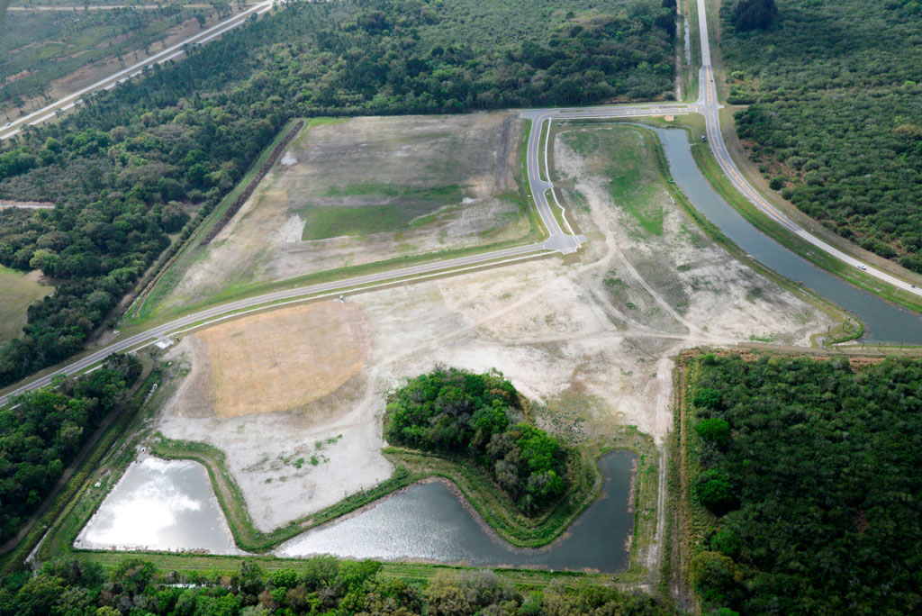
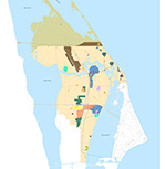
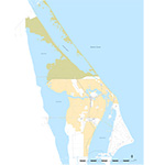
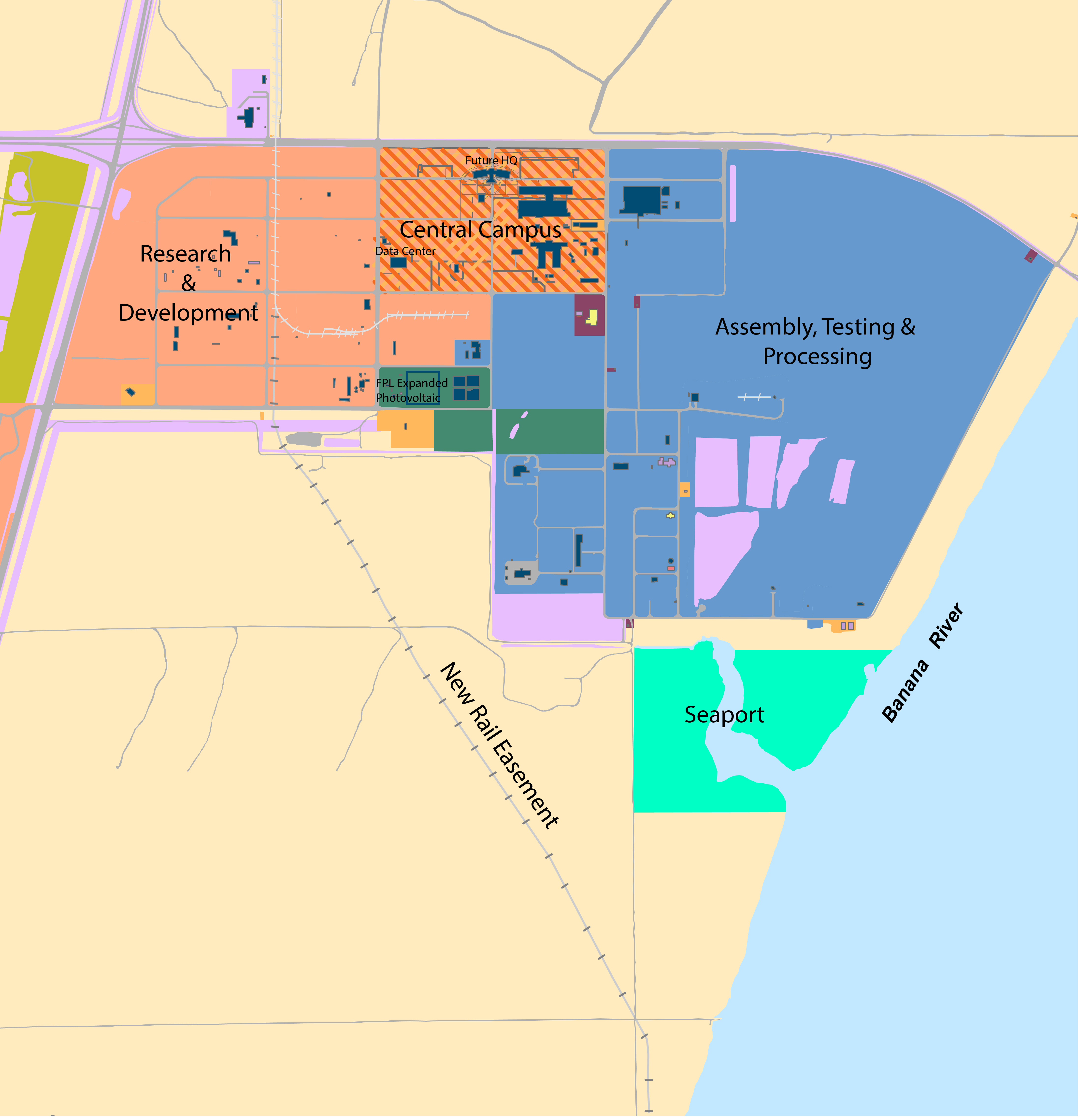
  • Future land use is guided by a land use component that includes land use planning initiatives.
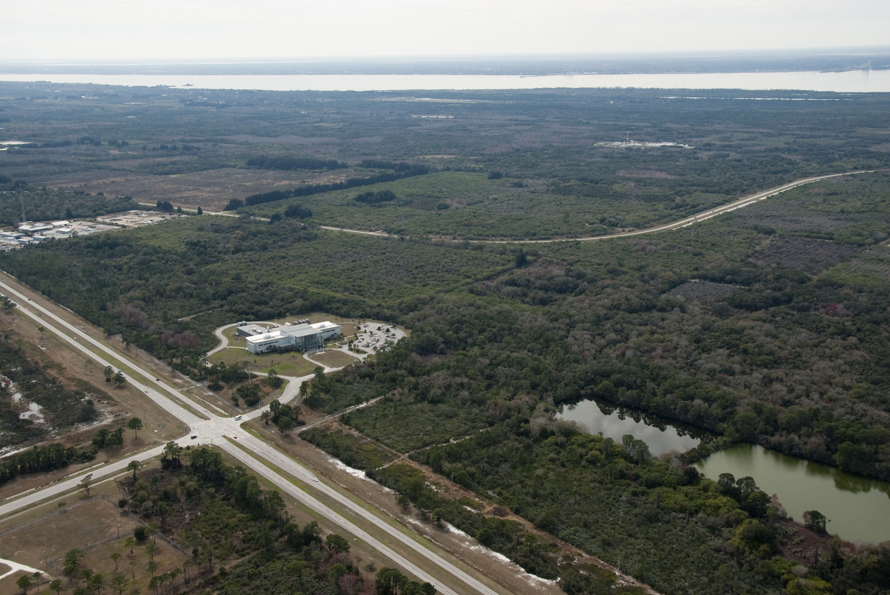
  • An analysis of the existing natural and built environment determined the highest and best use of land resources balanced with environmental sensitivity, operational requirements, and safety regulations. This comprehensive approach results in an efficient, environmentally-sensitive use of land area. Development suitability and capacity are the foundation of a compatible, safe, and efficient land use plan.
  • The Asset Plan incorporates facility initiatives for both vertical and horizontal infrastructure. In the Implementation Plan, these initiatives are coordinated with planning horizons and operating model stages.
  • The Center is supported by a quinti-modal transportation network and an extensive utility infrastructure supported by corresponding component plans and initiatives.

Transformation

  • Master planning initiatives and actions are correlated to planning horizons, as well as being linked to transformational stages that will facilitate the evolution of KSC to a multi-user spaceport.
  • Transformation stages include the necessary steps and activities, as outlined in the implementation component, to enable the transition to a focused business environment that will best support KSC’s transformation.
  • The transition from one stage to the next is not time-specific, but is largely dependent on federal funding, economic influences, and financial commitment from non-NASA entities.
  • Correlation of planning horizons and transformation stages are indicated to provide a context and framework to implement initiatives and actions, as well as fully leverage KSC's space market opportunities
  • .

Operational Plan Overview

A multi-user spaceport model is the foundation of KSC’s future operational state.

Small / nano satellites and commercial remote sensing satellites are also promising areas that may have fewer barriers to entry than larger payloads and launch vehicles.

Kennedy Space Center should strive to have all elements of the space flight industry supply chain at the Center, but focus initially on the ground support operation elements.

Strategic partnerships with federal agencies and universities to promote environmental sustainability, including space debris management, emergency management application and science, technology, engineering and math (STEM) education are “good-neighbor” / socially aware areas of focus.

KSC can initiate a more responsive focus to Economic Development Organization (EDO) programmatic efforts, while retaining the autonomy essential to fulfilling its space mission.

Kennedy Space Center should plan on a delayed demand surge through the medium-term and focus on diversifying the customer base across more aspects of the supply chain.

Publish 5-year plans or provide transparency of operations and business decisions; this is lacking in parts of the industry and could be an incentive for doing business with KSC.

Development Program

Overview

The Development Program describes the strategy that NASA must undertake to support the expansion of Non-NASA operations at KSC. As an extension of the Asset plan, the Development Program outlines a strategy to:

  • Sustain KSC’s ability to meet current and future mission requirements.
  • Consolidate NASA’s operations in fewer, more efficient and cost-effective facilities while maintaining technical capabilities.
  • Addresses Agency CRV reduction goals.

"Right sized” NASA operations at KSC are essential to support the multi-user spaceport model via a reduction in NASA’s footprint and consolidation of operations into specific functional areas. The development of the Central Campus is a initiative supporting the right-sizing efforts of KSC as a means to reduce operational overhead and support the transition to this multi-user model.

Future users and their activities are described in an effort to identify facilities and future projects required to support:

  • Continuing NASA Programs.
  • Future NASA Missions.
  • Anticipated Non-NASA Market Opportunities.

Projects to support continuing NASA Programs, as well as future and anticipated NASA Missions that may affect the KSC facility inventory are included in the Implementation component, including new facilities, as well as modifications to existing assets.

Programs

In the near term, the following continuing NASA Programs will be the principal users of KSC facilities:

  • International Space Station (ISS):is a habitable artificial satellite in low earth orbit, whose first component was launched in 1998. Currently, the mission is slated to conclude in the medium-term, but could be extended into the long-term planning time frame.
  • Commercial Resupply Services (CRS):provides for agreements between NASA and commercial entities to deliver cargo in support of ISS operations.
  • Orion Multi-Purpose Crew Vehicle (Orion MPCV):is a spacecraft that will serve as the primary crew vehicle for mission(s) beyond low Earth orbit. The spacecraft will serve as the exploration vehicle that will carry the crew to space, provide emergency abort capability, sustain the crew during the space travel, and provide safe re-entry from deep space return velocities. Orion will process hardware in the Operations & Checkout Building (O&C) to support the SLS flight rate.
  • Ground Systems Development and Operations (GSDO):processes and launches the next generation of launch vehicles and spacecraft in support of NASA’s exploration objectives, and develop the ground systems, infrastructure, and operational approaches to sustainably enable its mission.
  • Space Launch System (SLS):is an advanced, heavy-lift launch vehicle that will carry the Orion/MPCV, as well as important cargo, equipment and science experiments, to deep space destinations. SLS EM-1 will conduct an inaugural launch in FY18 and then one launch every 3 years thereafter.
  • Launch Services Program (LSP) :provides safe, reliable, and cost-effective scheduled launch services for NASA and NASA-sponsored payloads seeking launch on expendable launch vehicles (ELVs).
  • Commercial Crew Program (CCP):supports the development of a commercial capability to safely launch crew to the ISS and low-earth orbit.
  • NASA administrative uses:includes functions such as executive management, operations support, and human resources.

In the future, non-NASA entities are expected to conduct additional operations at KSC facilities.

  • A non-NASA user is anticipated to utilize the vertical launch capability of Pad 39A.
  • A non-NASA user will partially occupy the VAB to perform modifications or process flight hardware.
  • A small class “any launch any time launch vehicle will process vehicles and launch them from KSC at an estimated launch rate of 10 flights per year.
  • A non-NASA entity is anticipated to operate the Shuttle Landing Facility (SLF).
  • A commercial sub –orbital provider will fly 15 missions per year from the SLF.
  • A large winged vehicle carrying a horizontal payload will fly two to four missions per year from the SLF.
  • Unmanned Aerial Vehicle test flights will use the SLF.
  • Florida Power & Light (FPL) has a solar photovoltaic power facility located at KSC.
  • Delaware North and Visitor Centerwill continue to operate visitor facilities.
  • BRS will use the Parachute Refurbishment Facility (PRF) to establish a technical research and development center for advanced parachute systems and for manufacturing prototype systems.
  • PaR Systems will use Hangar N facility and its unique Non-Destructive Testing (NDT) equipment in Hangar N.
  • United Paradyne will use the Hypergol Manufacturing Facility (HMF) for in hypergolic storage operations and satellite fueling services.
  • Boeing will process the CST-100 in the Commercial Crew Cargo Processing Facility (formerly OPF3).

Facilities

NASA assets have been surveyed for potential use by non-NASA entities.

  • Some of these assets have been designated to remain dedicated to NASA Programs, while others can be dedicated to non-NASA use or designated as multi-use.
  • Assets financed by the State of Florida are indicated on the State Assets tab.
  • For more comprehensive information about KSC property holdings, refer to the Asset Plan.
  • The following assets are designated as NASA dedicated:


  • Launch Abort Systems Facility (LASF)

    Formerly named the Canister Rotation Facility, the Launch Abort Systems Facility consists of a 7,200-square-foot high bay building that contains a 100-ton bridge crane, canister support stands and access platforms, and associated site work utilities. The facility was designed to perform rotation of the canister from the horizontal position to the vertical and vice-versa. The facility is outfitted with power, lights, HVAC system, grounding and lightning protection, fire detection, fire protection, paging and area warning, telephone system, shop vacuum cleaning system and shop compressed air.

    SLS Mobile Launcher

    NASA's Space Launch System (SLS) heavy-lift launch vehicle will be carried to Launch Pad 39B at Kennedy Space Center in Florida atop an upgraded mobile launcher (ML) for missions to near-Earth asteroids, Mars and other new destinations in the solar system.

    The mobile launcher originally was constructed in 2008 and 2009 and now it will be structurally modified to meet requirements for NASA's new mission. The major work to be completed is widening the exhaust space in the mobile launcher base to support two solid rocket boosters and four main engines. Essentially, the exhaust hole will be increased from an approximate 24-by-24-foot space to a 32-by-65-foot space.

    Upgrades to the mobile launcher are part of Kennedy's efforts to expand its ground support infrastructure to support the SLS rocket and a variety of other launch vehicles. Another phase of upgrades will install the umbilicals, access arm and other ground support equipment on the mobile launcher. The flight test in 2017 will send an uncrewed Orion spacecraft into lunar orbit. NASA's asteroid initiative, which is part of the agency's proposed budget request for fiscal year 2014, will use SLS and Orion to send astronauts to study a small asteroid that will have been redirected robotically to a stable orbit near the moon.

    Operations & Checkout (O&C) Facility

    The Operations & Checkout (O&C) Facility, built in 1964, is located in Kennedy Space Center’s Industrial Area, immediately east of KSC’s Headquarters Building. The facility’s five-story high bay area was used for assembly and test of the Apollo spacecraft during the Apollo Program, was modified for use in support of the Space Shuttle Program, and, after a 2009 refurbishment, is currently being utilized as final assembly and testing facility for the Orion Multi-Purpose Crew Vehicle (MPCV). The Orion MPCV serves as the exploration vehicle that will carry the crew beyond low Earth orbit (LEO) and farther into space than ever before. The vehicle will provide emergency abort capability, sustain the crew during the space travel, and provide safe re-entry from deep space return velocities.

    The O&C Building contains 602,000 square feet (55,926 m²) of offices, laboratories, astronaut quarters and payload bay areas. The bay area is 650 feet long and a uniform 85 feet wide, except at the east end of the high bay where it is 38 feet, 5 inches wide. The bay is divided into a high bay area that is 175 feet long and 140 feet high, and a low bay area that is 475 feet long and 70 feet high. Attached to the bay area are three processing rooms, measuring about 13,800 square feet, with a 19-foot-high ceiling.

    A two-level, clean work area is 36 feet long, by 36 feet wide, by 38 feet high. This clean work area is serviced by a 1-ton bridge crane and numerous air-pallets used to move equipment without having to lift it. Equipment enters the bay area through the 40-foot-wide and 80-foot-high vertical lift doors at the east end, or through the shipping and receiving area. The building contains one large clean room with four payload 100,000 class test standards.

    Booster Fabrication Facility (BFF)

    The Booster Fabrication Facility (BFF), formerly the Solid Rocket Booster (SRB) Assembly and Refurbishment Facility (ARF) Complex was originally designed for SRB component manufacture, assembly and refurbishment. The 45-acre complex contains seven buildings constructed between 1986 and 1992. These include the Engineering and Administration Building, the Chiller Building, the Manufacturing Building, the Service Building and the Aft Skirt Test Building, all constructed in 1986. The Storage Building was constructed in 1988 and the Hazardous Waste Staging Building in 1992. The Manufacturing Building was used to fabricate process and refurbish inert or non-propellant SRB elements, including the forward and aft skirts, frustrums and nose caps, before delivering them to the Rotation Processing and Surge Facility (RPSF) for final assembly. The facility, now renamed the Booster Fabrication Facility, will be utilized via a partnership agreement by a commercial that will accomplish complete engineering development and risk reduction tests on the rocket that will serve as the SLS’s external booster stages. At the center of the SLS system is a liquid-fueled core stage modeled off the space shuttle’s big orange external fuel tank. Like the shuttle, the core stage will be flanked by two solid rocket boosters; later these solid boosters might be replaced by liquid-fueled ones. SLS will eventually scale up from its initial 70-metric-ton lifting capability to an evolved configuration with a 130-metric-ton lifting capability. This bigger version will have enough power and carry enough fuel to send the Orion capsule to deep-space destinations such as Mars.

    The Manufacturing Building contains an 80-foot by 250-foot central high bay with three-story wings to the north and south, two ordnance room cells with conditioned space, three TVC 100K build-up cells, and 9,260 square feet of TVC 100K clean rooms. The facility also has two thermal protection system (TPS) robotic paint cells with air turntables, two TPS cure cells, 10,260-square-foot TPS high bay conditioned prep and finish areas, and 5,800-square-foot Electronics and Instrumentation (E&I) conditioned electronics labs, as well as a machine shop. Other operations include the replacement of thermal protection on the SRB components, installation of electronic and guidance system, integration of SRB recovery parachutes, and automated checkout. It also is where the steering elements of the thrust vector control system are assembled and 2.1 Assembly and Refurbishment Facility (ARF) tested, and where the explosive devices for booster separation are installed. The ARF complex also contains engineering and administration and modular office buildings (with 106,500 square feet of total office space); two ground support equipment (GSE) service buildings; Aft Skirt Test Facility (ASTF) (with two test bays Class I, Div. 2, for hot fire testing); Hazardous Waste Storage Facility; Multi-Purpose Storage Building; MPSF Storage Facility (with 27,900 square feet of high bay storage, 2,980 square feet of high bay conditioned storage, 18,000 square feet of low bay conditioned storage and shipping, and receiving area and docks); and a supporting chiller building situated to the north.

    Payload Hazardous Servicing Facility (PHSF)

    The Payload Hazardous Servicing Facility (PHSF) is an 18,813-square-foot metal structure with a built-up roof that was built in 1986. It is a Level 4, class 100,000 clean room that can be used as a Payload Processing Facility (PPF) and/or a Hazardous Processing Facility (HPF). The facility can be used to process expendable launch vehicle payloads that have planetary protection cleanliness requirements or carry nuclear material.

    The PHSF complex has three main structures: 1) the PHSF, which contains a hazardous operations service bay and airlocks; 2) the Multi-Operations Support Building (MOSB) M7-1357, which contains an office area, support rooms and payload control rooms for the PHSF and Multi-Payload Processing Facility (MPPF) customers; and 3) the transporter storage building. The complex also has a fuel transfer building and an oxidizer shed.

    Hangar AE

    NASA’s Launch Services Program (LSP) utilizes Hangar AE for the Mission Director’s Center (MDC) and Launch Vehicle Data Centers (LVDCs) to independently monitor vehicle testing and launch of all expendable launches procured by the program.  LSP has also made the facility available to commercial and Department of Defense customers on a reimbursable basis, and has supported Delta II, Delta III, Delta IV, Atlas II, Atlas V, Pegasus, Taurus, Falcon 1 and 9, and Ares I-X launch vehicles in this facility.  About 700 square feet of office space within Hangar AE is currently configured for use by spacecraft customers. 

The following assets are designated as Non-NASA Dedicated.

Launch Complex (LC) 39A

Launch Pads 39 A & B were built in the early 1960s for the huge Apollo/Saturn V rockets. Both pads are octagonally shaped and share identical features. Pad A is located 18,159 feet from the Vehicle Assembly Building (VAB).

Pad A covers approximately ¼ square mile of land and is contained within a high chain link fence. Launches are conducted from atop a concrete hardstand located at the center of the pad that measures 390 feet by 325 feet. Pads A’s hardstand is 48 feet above sea level, respectively.

Pad A is capable of supporting testing, checkout, payload installation, servicing and launching.

Mobile Launcher Platform (MLP) 1, 2, and 3

The Mobile Launcher Platforms (MLPs) are two-story structures used to support vehicle stacking throughout the build-up and launch process during assembly at the Vehicle Assembly Building (VAB), while being transported to launch pads and also as the vehicle's launch platform. KSC's three MLPs were originally constructed for the Apollo program to launch the Saturn V rockets in the 1960s and 1970s, and remained in service through the end of the shuttle program in 2011 with alterations.

Each MLP weighs 3,730,000 kg (8,230,000 lb) unloaded. Each MLP measures 49 by 41 m (160 by 135 ft), and is 7.6 m (25 ft) high and is carried by the Crawler Transporter. The crawler-transporter carries the combined platform and vehicle to a launch site, and deposited them there together. Once the launch is completed, the crawler-transporter retrieves the empty MLP from the pad to be readied for its next use.

Originally designated the "Mobile Launcher," the MLP was designed as part of NASA's strategy for vertical assembly and transport of space vehicles. Vertical assembly allows the preparation of the spacecraft in a ready-for-launch position, and avoids the additional step of lifting or craning a horizontally-assembled vehicle onto the launchpad.

Orbital Processing Facilities (OPF) 1 and 2

Orbiter Processing Facilities (OPF) 1 and 2, built in 1979, are located near the west side of the Vehicle Assembly Building (VAB) in the Launch Complex 39 area. The OPF has two identical bays that are each 197 feet long, 150 feet wide and 95 feet high, and have 29,000 square feet of area.

A low bay separating the two bays is 233 feet long, 97 feet wide and 24.6 feet high. A 10,000-square-foot annex is located on the north side of the facility. Another 34,000-square-foot, three-story annex provides additional office space. In the high bays, a trench system under the floor contains electrical, electronic, communication, instrumentation and control cabling; hydraulic supply and return plumbing; gaseous nitrogen, oxygen and helium plumbing; and compressed air distribution plumbing. The two high bays have the ability to perform hypergol offloading and have emergency exhaust systems in case of hypergolic spills. The low bay houses areas for electronic equipment, a launch processing system interface, mechanical and electrical equipment shops and thermal protection system repair. The low bay also includes provisions for a communications room, offices and supervisory control rooms.

Supporting facilities include a 1,390 square foot Environmental Control System Building, a 1,390 square foot Environmental Control System Building, a 4,031 square foot ground support equipment storage building, a 145 square foot Hazardous Waste Staging Building, and a 3,201 square foot Pump House.

Commercial Crew and Cargo Processing Facility (C3PF)

Formerly referred to as Orbiter Processing Facility 3 (OPF 3), the Commercial Crew and Cargo Processing Facility (C3PF) is being transitioned into a modern and commercially friendly aerospace facility. The repurposing of this asset is the result of a first of its kind partnership between NASA-KSC and Space Florida whereby Space Florida has secured full long-term rights to operate, maintain, and improve the facility under purely commercial standards and make it available to commercial tenants. C3PF is ideally situated for commercial use, with direct access to the Shuttle Landing Facility that lies less than two miles away, as well as close proximity to all commercial, NASA, and Air Force launch pads located at Kennedy Space Center and Cape Canaveral Air Force Station.

Phase 1 of the renovations to the C3PF were completed in February 2013. This initial phase consisted of detailed design for facility modernization, as well as demolition of obsolete and abandoned Space Shuttle processing infrastructure including removal of the massive orbiter work stands in the High Bay to make room for a flexible and efficient clean-floor layout.

Hangar N

Hangar N is located at Cape Canaveral Air Force Station. The facility has a unique inventory of nondestructive test and evaluation (NDE) equipment, not available anywhere else, whose capability can be leveraged for current and future mission spaceflight support. Hangar N represents a world-class capability in both equipment and the highly-skilled people who are the key to that capability and is one of the most respected NDE centers in the industry.

Hangar N was used extensively during the space shuttle era. A partnership agreement is in place for use and operation of the Hangar N facility and its nondestructive testing (NDT) equipment. With the end of the shuttle flights, NASA had no immediate need for the operations taking place in Hangar N. However, as future programs start up, Hangar N's capabilities likely will be required. The partnership means the facility will be retained, but as a mutually shared facility and resource.

The Hangar N facility will continue to be used for inspection of large structures, as well as small commercial and aerospace components. Testing can be provided for both launch vehicles and commercial payloads, as well as for opportunities to support the needs of customers beyond the space business, for example general aviation, marine, energy and the petrochemical industries.

Crawler-Transporter 1

Crawler-Transporter 1 consists of four double-tracked crawler, each 3 meters (10 ft) high and 12 meters (41 ft) long. Each of the 8 tracks on the vehicle contains 57 shoes per track and each tread shoe weighs about .9 metric tons (one ton).

The Crawler-Transporter is powered by 16 traction motors powered by four 1,000 kw generators, driven by two 2,750hp diesel engines. Two 750 kw generators, driven by two 1,065 hp diesel engines are used for jacking, steering, lighting, and ventilating. Two 150 kw generators are also used for MLP power. Maximum speed is 1.6km (one mile) per hour loaded, and approximately 3.2 km (2 miles) per hour unloaded. The crawler burns 568 liters (150 gallons) of diesel oil per mile.

The height of the crawler is 6 meters (20ft) to 8 meters (26 feet) adjustable. The top deck is flat and square, about the size of a baseball infield, 27 meters (90 feet) on a side. Two operator control cabs, one at each end of the chassis, are used to control all crawler systems.

The following assets are designated as Multi-Use.

Crawler-Transporter 2

Crawler-Transporter 2 consists of four double-tracked crawler, each 3 meters (10 ft) high and 12 meters (41 ft) long. Each of the 8 tracks on the vehicle contains 57 shoes per track and each tread shoe weighs about .9 metric tons (one ton).

The Crawler-Transporter is powered by 16 traction motors powered by four 1,000 kw generators, driven by two 2,750hp diesel engines. Two 750 kw generators, driven by two 1,065 hp diesel engines are used for jacking, steering, lighting, and ventilating. Two 150 kw generators are also used for MLP power. Maximum speed is 1.6km (one mile) per hour loaded, and approximately 3.2 km (2 miles) per hour unloaded. The crawler burns 568 liters (150 gallons) of diesel oil per mile.

The height of the crawler is 6 meters (20ft) to 8 meters (26 feet) adjustable. The top deck is flat and square, about the size of a baseball infield, 27 meters (90 feet) on a side. Two operator control cabs, one at each end of the chassis, are used to control all crawler systems.

Shuttle Landing Facility (SLF)

The Shuttle Landing Facility (SLF) has a paved 15,000-foot runway, with a 1,000-foot-overrun on each end, 300 feet wide with 50-foot shoulders, and 16 inches thick. The SLF also includes a 550-foot by 490-foot parking apron on the southeastern end of the runway. The approach from the northwest is Runway 15; the approach from the southeast is Runway 33. South of the midfield point, east of the runway is the SLF Air Traffic Control Tower. The SLF is equipped with NAV/landing aids: TACAN, aim point-PAPI lights, ball/bar and distance to-go markers. Ground and ground-to-air communications, fire, crash, rescue and medical support are available.

Hangar AF

Hangar AF, located at Cape Canaveral Air Force Station, served as the Solid Rocket Booster (SRB) facility to support the Space Shuttle Program.

The facility may be used by the Ground Systems Development and Operations Program for production activities associated with the Space Launch System (SLS). The booster aft and forward skirts and case stiffener attach ring may be processed in the hangar, as well as refurbishment of the frustrum, before they are transferred to the Booster Fabrication Facility for buildup.

Launch Complex (LC) 39B

Launch Complex 39B is being reconfigured to support a clean pad concept. This concept will allow rockets to be transported to the pad on their own launcher, increasing versatility and flexibility and allowing the center to support multiple types of launch systems.

Rotation Processing Surge Facility (RPSF)

The Rotation Processing Surge Facility (RPSF) was constructed in 1984 specifically to rotate the Space Shuttle Solid Rocket Booster (SRB) segments, an operation vital to the preparation of the launch vehicle for its mission. The Rotation Processing Surge Facility has an area of 18,800 square feet, and has capabilities for solid motor receiving, rotation and inspection and also supports aft booster buildup.

Thermal Protection System Facility (TPSF)

The Thermal Protection System Facility (TPSF), built in 1988, is a two-story, 44,000-square-foot building in the Launch Complex 39 area. It provides a unique capability to manufacture thermal tiles. The TPSF is used to assemble, manufacture and repair thermal protection tiles, gap fillers and insulation blankets, used as protection from the searing heat of launch and reentry and the cold soak of space. These materials can sustain damage during a flight and must be inspected, repaired, or sometimes replaced for the next mission.

Vehicle Assembly Building (VAB)

The 1,831,549-square-foot Vehicle Assembly Building (VAB) is one of the largest and most-recognizable buildings in the world. It was built in 1965 to support assembly of Apollo/Saturn vehicles, and was later modified to support the Space Shuttle Program. The VAB covers eight acres and is 525 feet tall, 716 feet long, and 518 feet wide. The VAB has primary responsibility launch preparation operations and launch equipment maintenance and engineering. The VAB is split into high bay and low bay sections. The 525-foot-tall high bay contains four vehicle assembly and checkout cells (HB 1-4). Bays 2 and 4 face west and bays 1 and 3 face east located between six, 41-story towers (A-F) and a transfer aisle. The 210-foot-tall low bay is divided by the south end of the transfer aisle and contains eight works cells and four, six-story towers (K-N). All towers in the VAB contain operations and maintenance shops, general offices, materials storage space and equipment rooms. The facility is constructed of carbon structural steel framework, aluminum siding and luminous plastic exterior wall panels, concrete floors and foundation, and a combination of built-up and membrane roofing. The roof was replaced, and panels and vertical doors were refurbished between 2006 and 2009. Two large fold up doors are located at the east and west sides of the building and provide access to the high bay work cells. Large sliding doors located on the north and south ends of the building provide large equipment access to the transfer aisle. Numerous powered, coiling, roll-up doors are located throughout the facility. A total of 71 cranes are located throughout the building, including two, 250-ton bridge cranes in the transfer aisle.

Launch Control Center (LCC)

The four-story Launch Control Center (LCC) was built in 1966 to support the Apollo program. The building, 378 feet wide by 181 feet long, by 77 feet high is a secured facility, encompassing 230,436 square feet, with an access-controlled perimeter housing several individually accessed controlled centers. The LCC is connected to the east side of the Vehicle Assembly Building by an elevated, enclosed bridge.

The LCC is the centralized command and control facility within the Launch Complex 39 area, and directly and indirectly supports ground processing, launch and recovery. The fourth floor contains offices for launch operations personnel. Each firing room is equipped with the Launch Processing System (LPS) which monitors and controls most checkout and launch operations. In addition, KSC emergency response coordination is managed with specialized communications equipment within each firing room, including Paging and Area Warning System (PAWS) panels and specialized panels to support launch contingencies.

The Central Operations Facility (COF) provides duty office and emergency operations support, and houses the Emergency Operations Center (EOC) ride out location. The first floor is used for administrative activities and houses the Launch Complex 39 area utilities system control room and the Fire and Rescue Center. The second floor is occupied by the LPS Central Data Subsystem which consists of large scale computers that store data, including test procedures, vehicle processing data, master program library, historical data, pre- and post-test data analyses and other essential information for launch operations. The third floor is occupied by the four firing rooms and adjacent engineering support areas.

The LCC also is home to several unique centralized support control rooms and functions within its four stories, including RF and tracking, instrumentation, data reduction and evaluation, security and utility control. The LCC Complex Control Center provides facility systems control, Kennedy Complex Control System (KSCCS) for remote monitoring and control of field equipment associated with more than 150 systems, including high voltage, low voltage, oxygen deficiency monitoring system, pneumatics, heating, ventilation and air conditioning (HVAC), Firex and the Sound Suppression Water System.

Space Station Processing Facility (SSPF)

The Space Station Processing Facility (SSPF), built in 1992, consists of an administrative area, intermediate high bay area and high bay area. The online processing areas are located in the high and intermediate bay areas of the SSPF. Each footprint in the SSPF high bay provides up to 480V/100A of power, facility ground, chilled water, gaseous nitrogen (GN2), gaseous helium (GHe), high and low pressure venting, Operational Intercommunication Systems-Digital (OISD) communications, and compressed air. The building also was designed to accommodate a set of changing requirements. New footprint capabilities can easily be added via the tunnels underneath the high bay.

The offline processing areas are located near the office side of the SSPF building. They provide 20-foot- high ceilings and are capable of being a Clean Work Area. Offline processing areas provide similar features as the online areas, with the exception of cranes, chilled water, vents and fluids. The SSPF contains areas that were originally designed to be data centers. They have raised floors and are very easy to reconfigure with the necessary utilities for any type of activity to occur. The data center facilities typically have chilled water lines in them for low-profile air handlers to be readily installed. They also provide access to the facility uninterruptible power system (UPS). Environmental counters are located in each footprint in the high bay and intermediate bay to monitor and track particle counts and relative humidity. The high bay floor is capable of supporting very heavy loads. It also has sections which are seismically isolated, thus making it suitable for extremely precise measurements. The floor is very smooth in order to facilitate the use of air-bearing pallets which can enable very easy movement of large flight elements and stands.

The floor is conductive, which helps to reduce the risk of inadvertent electrostatic discharge. The air handling system in the online processing areas are capable of a minimum of four complete air changes in the high bay per hour, and can hold the temperature and humidity within strict specifications. The system runs at the capacity needed to keep the room at a 100,000 clean work area (CWA) specification. The Vapor Containment Facility (VCF), located adjacent to the east end of the intermediate bay, contains equipment to service flight hardware with NH3. Ammonia lines are brought into the high and intermediate bays on the east end, and built-in and portable environmental monitoring equipment is available.

The SSPF has approximately 20 offline laboratories. A typical offline lab will provide all of the capabilities as the online areas. Biology labs provide deep freezers, fume hoods, and other laboratory equipment and support services. The offline processing areas are located near the office side of the SSPF building. They have 20-foot- high ceilings and are capable of being a CWA, though they are rarely used as such. Offline processing areas provide similar features as the online areas, with the exception of cranes, chilled water, vents and fluids. The SSPF has redundant connections to the power grid as well as a backup generator. Also, battery UPS is provided through a combination of built-in facility systems and portable UPS units. UPS units are used to power systems that are sensitive to fluctuations in power quality, and to ensure that tests are not interrupted.

This facility is suitable for processing and assembly of payloads and spacecraft; however, certain hazardous commodities and operations are not permitted due to its proximity to existing inhabited buildings and the explosive and safety quantity distance requirements. The high bay is rated as a Class 1, Division 2, Groups C and D area.

Multi-Payload Processing Facility (MPPF)

The Multi-Payload Processing Facility (MPPF) complex includes three major structures. They are the MPPF, a 25,667-square-foot facility, which contains a high bay, low bay, equipment airlock, laboratory space and administrative offices; and two Payload Operation Control Centers (POCC).

The MPPF high-bay area maintains class 100,000 clean room conditions with facilities for checkout, assembly and processing of payloads. A single-story flight data communications room is connected to the MPPF on the southeast wall of the high bay and provides fully equipped racks and wall-mounted equipment to support the following communications system: Administrative and Data Communications, Broadband Cable Distribution System, Operational Intercommunications System-Digital (OIS-D), Paging and Area Warning, Timing, and Wideband/ Fiber Optics.

Other buildings are the Annex Building, which contains administrative offices, and a Multi-Operations Support Building (MOSB). The MOSB contains offices and payload control rooms. The MPPF is the main facility in the area, with a small fueling facility to the south, and a parking area to the north. The facility is surrounded by a security fence with three “crash-out” safety gates. The structure consists of a concrete foundation, steel frame and metal siding. The windows are single pane and the doors are steel. The flooring in the office area on the south side is carpet, and the flooring on the north side office areas and laboratory areas is vinyl tile. The flooring in the high bay area is concrete finished with a coating compatible with clean room environments.

Several Center facilities have been leveraged and financed via partnerships with the State of Florida for an investment total of $526.3 million, including $193 million at Kennedy Space Center and $333.3 million at Cape Canaveral Air Force Station.

  • A strong space program at Kennedy Space Center serves as a strong, unique economic driver for the State.
  • Due to the healthy, long-lasting relationship between the state of Florida and NASA, the State has contributed a significant amount of financial investment in recent years toward facilities at Kennedy Space Center.
  • Various, innovative types of funding mechanisms have been used to build upon this partnership, including Conduit Financing, Enhanced Use Leasing, and Real Property Use Permits.
  • The State hopes that financial support dedicated to these selected facilities will allow Kennedy Space Center to focus its spending on areas of greater need and also provide opportunities for the State to capitalize on the Center’s existing assets.
  • This type of financial partnership can also serve as a catalyst for Kennedy Space Center to continue its transformation into a multi-user spaceport complex, demonstrating the ability for multiple types of entities to conduct business on Center.
  • As the private space market continues to emerge, the state of Florida and NASA will continue to leverage each other’s assets and strengths to enable Kennedy Space Center to become a thriving spaceport that supports both government and commercial operations.


  • Lockheed Atlas V - Launch Complex (LC) 41

    • Agreement Type:Conduit Financing
    • Funded/Financed Amount:$294 Million
    • Lockheed Atlas V, LC-41

    Shuttle Launch Experience - Atlantis Museum

    • Agreement Type:Conduit Financing
    • Funded/Financed Amount:$40 Million
    • Exploration Park Thumbnail

    Apollo/Saturn 5 Display Facility

    • Agreement Type:Conduit Financing
    • Funded/Financed Amount:$25 Million
    • Apollo/Saturn5 Display Facility Thumbnail

    Boeing Horizontal Integration Facility (HIF) - Launch Complex-37

    • Agreement Type:Conduit Financing
    • Funded/Financed Amount:$24 Million
    • Boeing HIF LC-37 Thumbnail

    Space Commerce Way

    • Agreement Type:Enhanced Use Lease
    • Funded/Financed Amount:$5 Million
    • Space Commerce Way Thumbnail

    Exploration Park Phase 1

    • Agreement Type:Enhanced Use Lease
    • Funded/Financed Amount:$7.5 Million
    • Exploration Park Phase 1 Thumbnail

    Reusable Launch Vehicle (RLV) Hangar

    • Agreement Type:Real Property Use Permit
    • Funded/Financed Amount:$5 Million
    • RLF Hangar Thumbnail

    Commercial Crew and Cargo Processing Facility (C3PF)

    • Agreement Type:Real Property Use Permit
    • Funded/Financed Amount:$10 Million
    • Commercial Crew and Cargo Processing Facility

    Space Life Sciences Lab

    • Agreement Type:Real Property Use Permit
    • Funded/Financed Amount:$25.5 Million
    • Space-Life Sciences Lab Thumbnail

    Space Launch Complex (SLC) 46

    • Agreement Type:Real Property Use Permit
    • Funded/Financed Amount:$6.8 Million
    • Space Launch Complex 46 Thumbnail

    Launch Complex (LC) 40 Multiple Projects

    • Agreement Type:Space Florida Funding
    • Funded/Financed Amount:$6.5 Million
    • Launch Complex 40 Thumbnail

    Operations & Checkout Facility Refurbishment

    • Agreement Type:Space Florida Funding
    • Funded/Financed Amount:$35 Million
    • Operations & Checkoput Facility Thumbnail

    Hangar AO

    • Agreement Type:Space Florida Funding
    • Funded/Financed Amount:$2 Million
    • Hangar AO

Market Opportunities

The emerging commercial space flight market represents an opportunity for KSC to capitalize on its capabilities and history in order to capture this market as it develops. A competitive position has been formulated for KSC from a macro-level platform of information based on market research, KSC strengths, risks, competitors and customers. It represents the beginning of the commercialization process and will need to be refined as planning efforts continue and the market continues to evolve. The KSC competitive position presents a challenge for the Center to become one of the leading market participants moving the space flight market forward.

To fully leverage KSC to be at the forefront of space commerce, the following key concepts should be considered to best take advantage of emerging opportunities in the overall global space market:

  • Market Position – KSC should promote itself as a multi-user spaceport with unmatchable advantages. Implementing a hybrid strategy of a low cost and differentiated service provider will position it well in the space flight market. By focusing on its NASA programmatic responsibilities alongside the sub-markets of space transportation and technologies, satellite systems and payloads, ground and operations support systems, adventure tourism and clean energy, this will give KSC a solid base of economic activities. KSC should brand itself as a sustainable and socially aware spaceport that is enabling the space flight market to bring a whole new generation of explorers into space.
  • Design Reference Market Focus – In familiar NASA vernacular, the Design Reference Mission needs to become the Design Reference Market for the emerging space flight industry. This will represent a culture change from designing a launch vehicle or structure for one mission as missions are accomplished and have a defined end. Markets and customer relationships need to be sustained. Kennedy Space Center needs to operate with a focus on providing services to customers that support an ongoing and evolving relationship as the dynamic market develops.
  • Space Achievement Leader – The space flight industry is at an important crossroads, market participants are waiting for significant market movements to indicate a change in the economic environment. Until a dramatic technology breakthrough, an operationally-focused price change, or unforeseen demand occurs, the market will grow cautiously. KSC needs to be the leader in space achievement to bring forth needed technological improvements, foster customer-focused price changes and availability, while promoting new and compelling space flight market demand, to push this market forward towards its potential.

Based on identified movements, forecasts and benchmark data, the following are key market strategies that will be addressed over the near, medium, and long-term horizons to promote KSC’s success in the commercial space flight market. These strategies include:

  • Leverage human capital; people are the critical path.
  • Support commoditized launches.
  • Transition culture to Design Reference Market versus Design Reference Mission.
  • Refine space flight market manufacturing data.
  • Create a sustainable and socially aware brand.
  • Create a cluster of Ground Support Operations.
  • Partner with Economic Development Organizations.

Crucial as a foundation for the commercialization process, near term efforts should establish the working structure that will continue to operate into the medium and long terms. In the near term, KSC must resist moving quickly to marketing before fully understanding how it can best leverage its assets.

  • Launch Activity - Market demand forecasts indicate there will not be a surge in launches in the next five years. During this time frame, KSC should plan for no new, unscheduled launches to occur and for no changes in the pricing structure of the market. This level of launch activity supports a cautious marketing approach in the commercialization process.
  • Satellites - Small / nano satellites and commercial remote sensing satellites are also promising areas that may have fewer barriers to entry than larger payloads and launch vehicles. Customers in these submarkets, and ultimately the larger satellite market, fit well into KSC’s evolving commercialization plan. An added focus on accommodating emergency management applications may also reinforce the sustainable and socially aware brand at KSC.
  • Supply Chain - Kennedy Space Center should strive to have all elements of the space flight industry supply chain at the Center, but focus initially on the ground support operation elements. The presence of these activities will help generate a regional innovation cluster to encourage virtual collaboration, advanced manufacturing, and shared infrastructure. Having multiple facets of the space flight industry supply chain at KSC will make it more attractive to potential customers.
  • Strategic Partnerships - Strategic partnerships with federal agencies and universities to promote environmental sustainability, including space debris management, emergency management application and science, technology, engineering and math (STEM) education are ‘good-neighbor’ / socially aware areas of focus. This can add to KSC’s role as anchor tenant in the central Florida high tech economic cluster, leverages its assets and gives back to the local, regional and national community.
  • Collaboration - Collaboration should extend beyond traditional technical, governmental and institutional partners. The growing competition between localities for the infant commercial space industry necessitates the mobilization of local and state economic recruitment and development of capabilities to retain and grow the space industry in central Florida. With a newly adopted Center Master Plan in hand, KSC can initiate a more responsive focus to Economic Development Organization (EDO) programmatic efforts, while retaining the autonomy essential to fulfilling its space mission.
  • Commercial Business Model - KSC must also begin its transition to a commercialization model of business positioning, operation and asset management. By systematically aligning assets and capabilities to emerging market conditions and opportunities, KSC can successfully migrate into a new posture serving multiple customers and earning multiple revenue streams, while also retaining the flexibility to respond to the rapid evolution of the space industry.

Opportunities

Near-Term opportunities to take advantage of and/or leverage KSC’s position for successful business development of non-NASA opportunities include:

  • Establish a collaborative network of other space centers to ensure they are not competing against each other for international business.
  • Understand and align with DoD Commercial Space Launch Cooperation efforts.
  • Provide initial space tourism experiences, such as launch simulation.
  • Target opportunities within NASA’s Strategic Space Technology Investment Plan for implementation at KSC and the surrounding area to encourage local economic development through the transfer of NASA technology.
  • Seek partnership opportunities with state and local Economic Development Organizations to maximize the market response to KSC’s assets and strengthen the KSC reputation within the launch services supply chain.
  • Push standards and commonality into the space flight industry to commoditize launches, promoting an airport-like transportation model or flight test model.
  • Seek partnerships with small and nano-satellite operators, especially those with an emergency management focus.
  • Seek opportunities to partner with clean energy businesses and expand solar panel use when possible.

In the Medium-term the Commercial Crew Program will begin launches. Kennedy Space Center should continue to promote itself as the heavy-lift spaceport for both human space exploration and cargo. This is a distinct advantage that it has over other domestic launch facilities. KSC should seek the ability to adapt infrastructure to support additional launch systems of any class and new systems employing horizontal takeoff or recovery. Kennedy Space Center should plan on a delayed demand surge through the medium-term and focus on diversifying the customer base across more aspects of the supply chain.

Opportunities

Medium-term opportunities to take advantage of and/or to leverage, secure and expand KSC’s position in the non-NASA market include:

  • Ensure lessons learned in the near-term commercialization effort are adopted as the marketing program moves forward.
  • Brand KSC as the platform to quickly get companies access to space.
  • Establish a market reputation as fast and customer-focused.
  • Coordinate launch vehicle “piggy backing” with customers to pool launch costs.
  • Publish 5-year plans or provide transparency of operations and business decisions; this is lacking in parts of the industry and could be an incentive for doing business with KSC.
  • Get a visible representation as the new era of space exploration grows; KSC should be a brand so that when customers think of space flight, they think of KSC.
  • Continue to market KSC as a space tourism destination.
  • Expand KSC as a hub of space technology research and development, capturing an increased proportion of federal expenditures and collaborating with local partners to transfer technology to local businesses.
  • Establish an off-site, outreach office to meet with potential customers.

In-space services will drive spaceports to be more than just a launch facility. For the long term, KSC should have all elements of the supply chain present and continue to foster entrepreneurs, STEM education and other sustainable and socially aware partnerships and activities.

Initiatives + Actions

DP-1 | Define a sustainable end state.

  • Accurately define baseline assets required by NASA Programs together with their costs and potential funding.
  • Quantify the need for supplemental revenue from surplus assets and non-NASA entities.
  • Calculate the direct costs of maintaining, operating, and securing baseline assets (if this work has been done, obtain these figures).
  • Forecast revenues to be derived from baseline assets, including government funding, as the foundation for business decisions about non-NASA activities—what is the shortfall that must be made up with funding from other sources?
  • Create a related list of surplus assets that can be leased to non-NASA entities, either as dedicated non-NASA facilities or facilities to be shared with NASA Programs.
  • Calculate the direct costs of maintaining, operating, and securing surplus assets.
  • Forecast revenues to be derived from surplus assets by divesting or out-granting them.
  • Use this data to formulate a business case and consistent policy for the KSC commercialization program.

DP-2 | Develop non-NASA opportunities at KSC.

  • Identify Non-NASA programmatic launch related activities.
  • Identify non-NASA programmatic opportunities including facilities for space market supply chain vendors.
  • Recognize the potential revenue benefits associated with commercial non-programmatic offerings and broaden the KSC target market to include businesses that are not related to the space industry, but that may have high revenue potential.
  • Develop a cost / benefit analysis for these opportunities including estimated costs versus potential revenue.
  • Modify the business case to include both programmatic and non-programmatic non-NASA opportunities, including key objectives, supporting tactics, and performance metrics.

DP-3 | Leverage non-NASA funding for new projects whenever possible.

  • Periodically review the list of scheduled NASA-funded projects to incorporate them into the overall asset strategy; verify if overall Current Replacement Value (CRV) increases are acceptable and evaluate projects for potential funding by non-NASA entities.
Land Use Plan Main Image

Land Use Plan

Overview

The future land use plan promotes the highest, best and most efficient use of land area resources balanced with an understanding of development suitability and development capacity.

  • An understanding of existing land use characteristics forms the basis of an overall development framework to support continuing NASA programs and encourage future non-NASA opportunities.
  • The future Land Use Plan promotes compatible relationships between adjacent land uses, encouraging infill development and preserving environmentally sensitive areas
  • Land use classifications described following build upon their existing functions by recommending how land and facilities should be used in the future.

KSC Strategic Goals

Future Land Use outlines a development framework that will support the growth of the multi-user spaceport model. Building on the land use descriptions outlined in the Planning Conditions section, the Future Land Use Plan outlines where development can occur, how land can be used, and how to expand strategic capabilities to support KSC’s evolution to a multi-user spaceport. Through this approach, KSC is better able to promote smart development by better separating potentially hazardous operations from less-hazardous operational areas and non-NASA operations from NASA operations.

Implementing the future land considerations outlined in this Master Plan will promote the right-sizing of NASA operations at KSC and attract non-NASA investment by providing them more operational autonomy. The consolidation of NASA operations into a smaller geographic footprint is a major component of the Future Land Use Plan. Applying the Central Campus concept will allow NASA to recapitalize dispersed non-hazardous functions and capabilities into more efficient facilities with a smaller footprint. Likewise, directing future NASA and non-NASA operations into functional areas with well-defined activities will streamline safety and security considerations while promoting the maximum utilization of KSC’s horizontal infrastructure capacities. Finally, the Future Land Use Plan supports the expansion of the quinti-modal capabilities to provide increased support for all users of the multi-user spaceport.


Vertical Launch

Land Use Description - Vertical launch includes all facilities and land areas directly related to vertical launch operations, inclusive of launch pads 39A, 39B and 41, and anticipated future vertical launch facilities. It also includes immediately adjacent launch support facilities required to be operational at the time of launch. Quantity Distance (QD) arcs, launch hazard impact limit lines, other safety setbacks, and exposure limits are considered restrictions on the use of land adjacent to the Vertical Launch Area. Land within these restricted areas are not designated part of the Vertical Launch land use.

Future Development - In keeping with previous recommendations from the 1966, ‘72 and ‘77 KSC Master Plan’s, when the market demands an expansion of vertical launch capacity this Plan recommends additional vertical launch pads to be sited to the north of existing 39B, as pads 39C and 39D respectively. In addition, a 2007 Vertical Launch Site Evaluation Study concluded that a vertical launch pad could also be sited to the south of 39A and to the north of pad 41 to accommodate small launch vehicles. Due to the nature of these activities, QD arcs, launch hazard impact limit lines, other safety setback, and exposure limits requirements will be imposed for safe operations.

Vertical Landing

Land Use Description - The ability to accommodate vertical landing capability will promote reusability of space flight hardware and significantly lower the price point for access to space.

Future Development - In anticipation of these advances, KSC has designated areas along it’s north eastern secure boundary as lands that could accommodate such activity. Due to the nature of these activities, QD arcs, landing hazard impact limit lines, other safety setback, and exposure limits requirements will be imposed for safe operations.

Horizontal Launch and Landing

Land Use Description - Horizontal Launch and Landing includes pavements, infrastructure, facilities and land area directly related to horizontal launch and landing operations. Horizontal Launch and Landing includes all paved runway surfaces, aprons, or similar runway features primarily associated with the Shuttle Landing Facility. Imaginary surfaces related to airfield safety clearances consistent with FAA clearance criteria and requirements, Quantity Distance (QD) arcs, launch and landing hazard impact limit lines, other safety setbacks, and exposure limits are considered restrictions on the use of land adjacent to the Horizontal Launch and Landing Area. Land within these restricted areas are not designated part of the Horizontal Launch and Landing land use.

Future Development - Apron areas supporting the Shuttle Landing Facility (SLF) are intended to be expanded to accommodate future horizontal launch and landing activities and customers along with associated support facilities. Expansion of these capabilities is expected to be consistent with the recommendations outlined in the 21st Century Launch Complex Area Development Plan (April 2012). Initial development will be focused on the east side of the runway and future development, if required, will be accommodated to the west side. Over the long-term, as the market and emerging technology may demand, additional horizontal launch infrastructure can be constructed in an area identified just south of Beach Road that will support an east-west horizontal launch capability. Due to the nature of these activities, QD arcs, launch and landing hazard impact limit lines, other safety setback, and exposure limits requirements will be imposed for safe operations.

Launch Operations and Support

Land Use Description - Launch Operations and Support includes facilities and associated land areas essential to supporting a mission during launch and flight, including command, control and compilation, evaluation and communication of the data associated with launch vehicle activities. Storage of propellants and munitions is also included in this classification. Quantity Distance (QD) arcs, other safety setback, and exposure limits are considered restrictions on the use of land adjacent to the Launch Operations and Support Area. Land within these restricted areas are not designated part of the Launch Operations and Support land use.

Future Development - Launch Operations and Support areas will be expanded, if needed, to accommodate future launch activities and the requirements of NASA and Non-NASA operations.

Assembly, Testing and Processing

Land Use Description - Assembly, Testing and Processing includes facilities, operations and land areas that are essential to space vehicle component assembly, integration and processing prior to launch. Laboratories, material support and interface testing to achieve final assembly, test and closeout to prepare and test payloads, space systems and systems components for flight and integration, which may include hazardous commodities, are also included in this clarification. Primary uses and facilities support both government and commercial capabilities for payload assembly, integration, and processing; the development and testing of launch vehicle or spacecraft equipment at the component or system level; post-flight servicing and refurbishment activities; and spaceport infrastructure and operations. Secondary uses and facilities include associated and compatible manufacturing, logistics, or technical support functions. Quantity Distance (QD) arcs, other safety setback, and exposure limits are considered restrictions on the use of land adjacent to the Assembly, Testing and Processing Area. Land within these restricted areas is not designated part of the Assembly, Testing and Processing land use.

Future Development - Assembly, Testing and Processing areas can be expanded to the north of the existing developed areas in the VAB Area to accommodate future Assembly, Testing and Processing functions. Development in the expanded areas will require seawall construction to comply with sea level rise criteria. Land areas in the vicinity of Contractors Row previously designed as Support Services are designated as Assembly, Integration and Processing in support of future needs and requirements. In the Industrial Area, Assembly, Testing, and Processing payload functions can be expanded to the north and east of their current concentration to accommodate increased payload processing and testing. Due to the nature of these activities, QD arcs, other safety setback, and exposure limits requirements will be imposed for safe operations.

Central Campus

Land Use Description - The area identified as Central Campus will be utilized as a means to consolidate NASA operations into a smaller more cost-effective operational footprint. The Central Campus land use includes all non-hazardous NASA operations that occur in support of NASA missions and programs. Ideal land uses for consolidation include: Administration, Research and Development, and non-hazardous Support Services.

Future Development - The area will be populated over the planning horizon and beyond to support any non-hazardous new NASA development in support of NASA programming and/or as part of the KSC’s recapitalization process. Facilities that are meant to be relocated to Central Campus through recapitalization efforts are NASA facilities being utilized for Administration, Research and Development, and non-hazardous Support Services functions that have aging-related operational inefficiencies and excessive maintenance requirements whose relocation would support decreased CRV and O&M costs.

Utility Systems

Land Use Description - Utilities Systems land use classification includes land and facilities associated with KSC utilities infrastructure and systems (i.e., water, wastewater, gas, electrical, chilled water, medium temperature hot water, communications and sewer systems). Utility easements help to define patterns and impacts associated with the development of utility systems and the overall land use pattern. Communications lines for line-of sight are identified as visual corridors associated with communications components.

Future Development - Improvements and expansion of utilities systems proposed to support future development are outlined under projects in the implementation component.

Administration

Land Use Description - Administration includes facilities supporting operations management and oversight activities. Administrative functions/uses associated with management are more focused in the Industrial Area. A subset of administration applies to administrative functions that are adjacent to and in support of assembly, integration and processing operations.

Future Development - Facilities supporting Administration functions are planned to be recapitalized into the Central Campus area over the near, medium, long-term and beyond. Consolidation of non-hazardous facilities, such as administration facilities, is a necessary precursor to the consolidation of NASA operational areas to support a multi-user spaceport.

Support Services

Land Use Description - Support Services includes all functions other than administration that provide management and oversight of KSC operations and services provided for overall KSC benefit, including operations and maintenance. Operations and maintenance land uses include supply, storage, facilities maintenance, motor pool, service stations, railroad, reclamation areas, roads and grounds maintenance and sanitary landfill facilities. Service land uses include: access control and entry gates; fire protection facilities and training areas; security facilities and related training areas; child development and care; training and conference; dispensary; data processing; environmental and occupational health; food service and photo operations facilities.

Future Development - Future development of non-hazardous Support Services facilities and recapitalization of inefficient existing facilities are intended to occur in the Central Campus area to support right-sizing efforts and the consolidation of NASA operational areas.

Public Outreach

Land Use Description - The Public Outreach land use classification includes facilities and associated land areas that promote an educational, research or informational connection between the community and KSC. Examples of Public Outreach use include public reception/welcome centers, tour facilities, display and education areas, museums, memorials, launch viewing areas, recreation areas and conference centers.

Future Development - Existing Public Outreach areas are retained and designated in the Future Land Plan promoting educational, research or informational connections between the community and KSC.

Recreation

Land Use Description - Recreation areas include parks, outdoor fitness, athletic fields, recreation buildings, centers and clubs. Examples of recreation land uses include KARS Park North and KARS Park South complexes. Coastal beaches and supporting facilities are part of the Cape Canaveral National Seashore and are classified as Operational Buffer/Public Use. Camping, fishing, picnic and related outdoor activity areas associated with the Merritt Island National Wildlife Refuge are also classified as Operational Buffer/Public Use.

Future Development - Additional Recreational land use areas are not planned, so future development and/or expansion of recreational functions, if necessary, will occur within the already established recreational land areas.

Research and Development

Land Use Description - The Research and Development (R&D) land use classification includes non-program specific laboratories, related facilities and associated land areas that perform research, experimentation and testing in support of developing new technologies, procedures and products to enhance existing and future programs at KSC.

Light industrial and manufacturing functions, as well as commercial uses may also be accommodated within R&D land use areas. Integration of educational institutions offering advanced degrees in disciplines supporting space-related research and development activities provide added enhancement and support reinforcing R&D collaboration between KSC, private industry and the educational community. Examples of R&D land uses include chemical, physical standards and laser testing laboratories; missile research and testing facilities; centers for experimentation; innovative science and technology; and life science activities accommodated in Exploration Park.

Future Development - Additional R&D development will be directed to the Industrial Area with non-NASA development designated for west of C Avenue or within Exploration Park in order to provide separation from NASA operational areas. New NASA R&D facilities and recapitalization of existing NASA R&D facilities will be directed to Central Campus in the designated area east of C Avenue.

Seaport

Land Use Description - The Seaport land use classification includes: port, harbor, wharves, docks and associated land areas to accommodate authorized delivery or embarkation of materials, equipment or people via access to the mainland through means of sea going vessels. Land areas contiguous to wharves and docks that are used for the staging, off-loading, transfer and storage/processing of materials, equipment or people are also classified as Seaport land use.

Future Development - Additional land areas are designated as Seaport to support future development of the water-based transportation capability to further leverage quinti-modal functionality and to also capitalize on surrounding area water accessibility and linkage to Port Canaveral.

A future Seaport/multi-modal facility is designated to the west of the SLF to provide water access in support of horizontal launch and landing operations via the Indian River.

An additional Seaport is designated to the south of the Assembly, Integration and Processing Area on the east side of the Industrial Area. This Seaport will provide water access to support all operations and functional areas within the Industrial Area.

Renewable Energy

Land Use Description - Land areas designated to accommodate varying forms of renewable energy are designated Renewable Energy land use. Corresponding to fallow agricultural land and other underutilized property, land areas designated as Renewable Energy also includes research and production facilitating KSC’s goal for achieving increased on-site generation of its power from renewable sources. This includes current and future accommodation of solar array fields, as well as other emerging renewable energy technologies that may be developed in the future.

Future Development - Former citrus groves that have now become fallow are designated as future land areas to accommodate Renewal Energy uses. Additional land for renewable energy use is also designated in the Industrial Area and can be accommodated as secondary uses in parking lots . (see Renewal Energy in utilities section )

Operational Buffer

Land Use Description - Buffer land area is submerged, vulnerable to inundation by rising water whether the result of storm event or climate change, or is a high-value uplands habitat for species of critical concern, such as the Florida scrub jay. Two sub-categories of Operational Buffer are designated, including conservation and public use.

Operational Buffer/Public Use

Operational Buffer/Public Use areas correspond to publicly accessible areas of Merritt Island National Wildlife Refuge and the Cape Canaveral National Seashore for recreational use in the northern portion of KSC, as a conditional use subject to the operational activities associated with KSC’s mission.

Operational Buffer/Conservation

Operational Buffer/Conservation areas correspond to land areas in the southern portion of KSC that may never have been developed, or sites that may have reverted to a natural environment over the years.

Future Development - Development in Operational Buffer areas may include infrastructure, operations of low impact, or small footprint facilities that may be required for support of space launch or landing operations.

Performance Zoning

The Future Land Use Plan provides for functionally efficient, compatible, safe, secure and environmentally sensitive development. Added regulatory guidance is also needed to fully enable key operational characteristics of a successful multi-user spaceport. Many of these operational characteristics are required by commercial industry to provide the most efficient and economical operations while addressing safety and access requirements for, often, hazardous operations. Two variations of performance zoning can be utilized to support the proliferation of Non-NASA entities at KSC, including Commercial Operations Zones (COZ) and Industrial Operations Zones (IOZ).

The COZ/IOZ concept was initiated by feedback from non-NASA entities interested in bringing operations to KSC but wanting to use existing company safety regulations instead of NASA's existing safety requirements. In support of the growth of non-NASA operations at KSC, NASA KSC Safety and Mission Assurance (S&MA) released two new volumes to augment the existing KSC safety regulations. The three volumes encompass three levels of NASA oversight depending on the level of risk of non-NASA operations to NASA personnel and property. The three levels include:

  • Volume 1: Safety Procedural Requirements for Civil Servants/NASA Contractors.
  • Volume 2: Safety Procedural Requirements for Partner Organizations Operating in Joint-Use Facilities (Supporting the IOZ Concept).
  • Volume 3: Volume 3: Safety Procedural Requirements for Partner Organizations Operating in Exclusive Use Facilities (Supporting the COZ Concept).

The Commercial Operations Zone (COZ) concept was described in the approved Future Development Concept as a tool for KSC’s transformation into a multi-user spaceport. A COZ is defined as:

  • An area with no identified current or future NASA programmatic need (e.g. SLS, Orion, etc.) where commercial (or government) entities can do business in accordance with federal/state/local laws and commercial standards in which NASA has minimal oversight, in that it does not enforce these laws or standards.
  • A COZ designation can only apply to non-NASA exclusive-use facilities where operations are performed solely by non-NASA personnel which is sufficiently isolated from NASA operations to allow minimal NASA regulatory control.

Future Implementation Activities - The COZ concept serves as an important aspect of the growth of KSC as a multi-user spaceport. Over the near-term, as The Plan is implemented, the COZ concept will be further developed to describe:

  • The framework necessary for the implementation of COZs
  • Models for how COZs will be defined for different classifications of facilities and land use
  • A policy that outlines the specifics of the COZ concept as it pertains to each Functional Area within the Future Land Use Map (e.g. a COZ that requires a QD Arc has different circumstances and more risk than a COZ within a Research and Development designated area)

Industrial Operating Zones are areas designated where both Commercial and NASA operations jointly occur and where NASA regulatory criteria will apply. IOZ’s and the scope of their requirements are usually accompanied with agreements between NASA and a commercial entity. Currently, KSC has two IOZ’s: O&C Hi-Bay (with Lockheed Martin) and the Booster Fabrication Facility (with ATK).

Planning Actions

LUP-1 | Provide for a balanced mix of uses while promoting the highest and best use of developable land.

  • Fully leverage all existing facilities and developable land to capitalize on diversified development opportunities.
  • Reinforce the overall asset planning strategy by monitoring ongoing functional area planning to evaluate how much land NASA should own over the near, medium, and long term.
  • Designate land area for an expanded development program to ensure the compatibility of diverse activities.
  • Consolidate like functions and uses within designated functional areas to promote efficient land use and save on operations and maintenance and energy costs.
  • Group commercial activities into Commercial Districts to reinforce the concept of a launch-related supply chain.
  • Any new hazardous activities will be placed in existing QD arcs.

LUP-2 | Emphasize existing development boundaries and reinforce buffers between developed and undeveloped land.

  • Promote infill development in areas that are already serviced by existing infrastructure rather than building horizontal infrastructure and new construction on undeveloped land.
  • Plan new development to be compact and incorporate sufficient buffers.
  • Construct a support road and railroad spur in the Contractor Road area to fully leverage the high ground.
  • Locate future Research and Development expansion within the Industrial Area to take advantage of existing roads, utilities, and drainage basins.
  • Fully leverage and expand development opportunities to the east and west of the Shuttle Landing Facility to enhance the value of this unique asset.

LUP-3 | Promote environmentally sensitive future development.

  • Concentrate development on high land elevations to create compact, efficient functional areas that are not vulnerable to inundation by storm surges or future sea level rise.
  • Construct a seawall to raise the developable land area adjacent to the Vertical Assembly Building and create an elevated area for future mission-critical facilities.
  • Integrate new drainage basin areas that capture surface water in the Industrial Area to support future development.

LUP-4 | Promote more on-site renewable energy to become more energy independent and reduce greenhouse gases.

  • Allocate additional land for renewable energy use within the Industrial Area, south of Research Park (north of the existing renewable energy area), and on land north of NASA Parkway and west of Kennedy Parkway in fallow orange grove areas and other underutilized open spaces.
  • Install charging stations for electric vehicles throughout the Center, powered by photovoltaic fields on renewable energy sites.

LUP-5 | Sustain uninterrupted existing and provide additional launch capability to support emerging markets.

  • Provide additional launch capacity with new vertical launch pads C and D and launch pad 42 north of existing pad 41.
  • Construct a new Vertical Assembly Building and crawler-way connection for future vertical assembly requirements.
Asset Plan Main Image

Asset Plan

Overview

The Asset Plan describes a sustainable end state for the Kennedy Space Center (KSC) that supports continuing NASA programs, projected future missions, and identified commercial needs.

  • A key element of this plan is the right-sizing of assets from a Shuttle programmatic NASA-owned facility inventory to a reduced inventory of facilities and infrastructure that are appropriately sized to meet future NASA program and commercial mission requirements.
  • The Asset Plan balances the continuing operational needs of remaining NASA programs with decreasing budgets and the business case for the KSC end state as described in the Development Program.
  • As part of the Asset Plan, facility focused planning actions are organized and described for all functional areas.

Approach

Historically, the metric used to gauge economic sustainability within the Agency is the aggregate Current Replacement Value (CRV). CRV is indicative of the extent of real estate holdings and the corresponding costs to operate and maintain these facilities. The NASA Office of the Inspector General has identified a total-agency CRV reduction goal of 10 percent by 2020 and 15 percent by 2055 distributed among the 10 NASA centers. While no specific CRV reduction targets are in place for KSC, it is generally acknowledged that CRV should be reduced proportional to declining operating budgets.

  • While CRV reductions are an important data point in determining the fiscal health of the Agency and Center, KSC believes that the CRV methodology and subsequent goals only tell a partial story in the work that KSC is doing to evolve to a multi-user spaceport. For instance, a real property asset, and the operation and maintenance of a facility may be transferred to another non-NASA entity, but the CRV of the asset still remains on the government ledger.
  • Traditionally, the only way to reduce CRV is through demolition. While KSC recognizes that there are many facilities that need to be shed, many of the assets are one of a kind, and demolition is not the only solution to right-size KSC’s asset base.
  • In this phase of change, the Center will continue to form partnerships and try to expand its authority to allow for the public-benefit conveyance of real property assets in order to preserve the Center’s and nations crucial launch infrastructure.
  • The KSC multi-user spaceport of tomorrow will be composed of NASA, State and commercially owned and operated facilities. Facilities and infrastructure will be funded through a mix of federal, state and commercial dollars. The federal government, state government and private investments will all be used in concert with one another for the benefit of the spaceport. KSC will continue to seek ways to allow for the offset of funds from other entities to be used with its appropriation.
  • Recommended planning actions affecting facility status and the resulting changes in CRV are identified for all facilities organized by function areas during the planning timeframe of 2013 through 2032.
  • The Asset Plan to support KSC’s transition also includes new projects and anticipated funding sources, which are described in the Implementation Plan.

Status Categories

The Asset Plan analysis classifies facilities and infrastructure into six status categories:

  • Active – real property required for continuing NASA programs. The facility is actively used by NASA programs and is maintained in an operational state.
  • Mothballed – an inactive facility maintained by NASA. The facility has been temporarily deactivated and building systems are appropriately maintained to prevent excessive deterioration.
  • Out-Granted – real property leased to non-NASA entities; NASA retains ownership. Lease terms vary, but often the leasing entity is responsible for measurable direct costs such as utilities; for purposes of this analysis, the leasing entity is responsible for operations and maintenance cost.
  • Divested – title transferred by NASA for use by other non-NASA entities. The facility is actively used and is maintained in an operational state by the leasing entity. Currently there are few properties that are truly divested, although this course of action is recommended for selected properties.
  • Abandoned – an inactive facility, minimally maintained by NASA. The facility has been permanently deactivated and is slated for demolition at the earliest practical date; until the facility is demolished, it may be necessary to maintain the exterior of the facility in a minimally aesthetically acceptable condition; all utilities have been secured and disconnected.
  • Demolished – facility will be torn down within the timeframe indicated.

Functional Area Plans

Existing development is characterized by concentrations of functions and activities, which also form the basis for an organizing framework to describe existing uses, patterns and relationships. Functional areas are also a means to describe future asset and facility strategies. Facility and asset specific planning actions corresponding to planning timeframes, providing additional detail within land use areas/districts correlated to facility footprints and site plans area organized by functional area.

Concentrations of functions and uses correspond to the following functional areas:

Industrial Area + Central Campus

Industrial Area Plan Map | Existing 2013 Thumbnail
Existing 2013
Industrial Area Plan Map | Current Facility User Thumbnail
Program
Industrial Area Plan Map | Status 2017 Thumbnail
Status 2017
Industrial Area Plan Map | Status 2022 Thumbnail
Status 2022
Industrial Area Plan Map | Status 2032 Thumbnail
Status 2032
Industrial Area Plan Map | Future 2032 Thumbnail
Future 2032

Future development in the Industrial Area is characterized redevelopment and enhancement of the Central Campus area and expansion of Research and Development and Assembly, Testing and Processing functions.

  • The Central Campus expansion is a means to consolidate NASA operations into a smaller more cost-effective operational footprint with uses to predominately include non-hazardous NASA operations that will continue to occur in support of NASA missions and programs.
  • Facilities that will be relocated to Central Campus through recapitalization efforts are NASA facilities being utilized for Administration, Research and Development, and Support Services functions that have aging-related operational inefficiencies and excessive maintenance requirements whose relocation would support decreased CRV and O&M costs.
  • Additional land area is designated to accommodate expanded Research and Development activities, leveraging the momentum of Exploration Park.
  • Expanded payload processing functions will be accommodated in an expanded Assembly, Testing and Processing area.
  • A new seaport will provide direct access to the sea via the Banana River through Port Canaveral and an extended rail line.

Exploration Park

Exploration Park Area Plan Map | Existing 2013 Thumbnail
Existing 2013
Exploration Park Area Plan Map | Current Thumbnail
Program
Exploration Park Area Plan Map | Status 2017 Thumbnail
Status 2017
Exploration Park Area Plan Map | Status 2022 Thumbnail
Status 2022
Exploration Park Area Plan Map | Status 2032 Thumbnail
Status 2032
Exploration Park Area Plan Map | Future 2032 Thumnnail
Future 2032

Additional land area is designated as Research and Development to build upon the momentum and expansion potential of Exploration Park, also linking to newly developed Research and Development areas adjacent to Central Campus.

Vehicle Assembly Building (VAB) Area

VAB Area Plan Map | Existing 2013 Thumbnail
Existing 2013
VAB Area Plan Map | Current Thumbnail
Program
VAB Area Plan Map | Status 2017 Thumbnail
Status 2017
VAB Area Plan Map | Status 2022 Thumbnail
Status 2022
VAB Area Plan Map | Status 2032 Thumbnail
Status 2032
VAB Area Plan Map | Future 2032 Thumbnail
Future 2032

Additional land area is designated as Assembly, Testing and Processing areas to provide support to anticipated increased future launch activity. Construction of sea walls will mitigate against sea level rise.

Contractors Road Area

Contractors Road Area Plan Map | Existing 2013 Thumbnail
Existing 2013
Contractors Road Area Plan Map | Current Thumbnail
Program
Contractors Road Area Plan Map | Status 2017 Thumbnail
Status 2017
Contractors Road Area Plan Map | Status 2022 Thumbnail
Status 2022
Contractors Road Area Plan Map | Status 2032 Thumbnail
Status 2032
Contractors Road Area Plan Map | Future 2032 Thumbnail
Future 2032

Expanded land area is provided to accommodate increased Assembly, Testing and Processing support to anticipated increasing future launch activity.

Expanded Vertical Launch Area + Launch Complex - 39B

Launch Complex 39B Area Plan Map | Existing 2013 Thumbnail
Existing 2013
Launch Complex 39B Area Plan Map | Current Thumbnail
Program
Launch Complex 39B Area Plan Map | Status 2017 Thumbnail
Status 2017
Launch Complex 39B Area Plan Map | Status 2022 Thumbnail
Status 2022
Launch Complex 39B Area Plan Map | Status 2032 Thumbnail
Status 2032
Launch Complex 39B Area Plan Map | Future 2032 Thumbnail
Future 2032

Launch Complex 39B is being reconfigured to accommodate the Space Launch Systems.

In keeping with previous recommendations from the 1966, ‘72 and ‘77 KSC Master Plan’s, when the market demands an expansion of vertical launch capacity, this Plan recommends additional vertical launch pads to be sited to the north of existing 39B, as pads 39C and 39D respectively.

Launch Complex - 39A

Launch Complex 39A Area Plan Map | Existing 2013 Thumbnail
Existing 2013
Launch Complex 39A Area Plan Map | Current Thumbnail
Program
Launch Complex 39A Area Plan Map | Status 2017 Thumbnail
Status 2017
Launch Complex 39A Area Plan Map | Status 2022 Thumbnail
Status 2022
Launch Complex 39A Area Plan Map | Status 2032 Thumbnail
Status 2032
Launch Complex 39A Area Plan Map | Future 2032 Thumbnail
Future 2032

A non-NASA user is anticipated to utilize the vertical launch capability of Pad 39A.

Small Vehicle Launch Site Area

A new Small Vehicle Launch site area is proposed to the south of 39A and to the north of pad 41 consistent with a 2007 Vertical Launch Site Evaluation Study.

Vertical Launch Area Map Thumbnail
Vertical Launch Areas

Shuttle Landing Facility (SLF) Area

SLF Area Plan | Existing 2013 Thumbnail
Existing 2013
SLF Area Plan | Current Thumbnail
Program
SLF Area Plan | Status 2017 Thumbnail
Status 2017
SLF Area Plan | Status 2022 Thumbnail
Status 2022
SLF Area Plan | Status 2032 Thumbnail
Status 2032
SLF Area Plan | Future 2032 Thumbnail
Future 2032

Apron areas supporting the Shuttle Landing Facility (SLF) will be expanded to accommodate future horizontal launch and landing activities and customers along with associated support facilities. Expansion of these capabilities is expected to be consistent with the recommendations outlined in the 21st Century Launch Complex Area Development Plan (April 2012). Initial development will be focused on the east side of the runway and future development, if required, will be accommodated to the west side. Over the long-term, as the market and emerging technology may demand, additional horizontal launch infrastructure can be constructed in an area identified just south of Beach Road that will support an east-west horizontal launch capability.

Central Telemetry Area (TEL IV)

CCAFS Area Plan Map | Current Thumbnail
Existing 2013
CCAFS Area Plan Map | Current Thumbnail
Program
VIC Area Plan Map | Current Thumbnail
Status 2017
VIC Area Plan Map | Status 2022 Thumbnail
Status 2022
VIC Area Plan Map | Status 2032 Thumbnail
Status 2032
VIC Area Plan Map | Future 2032 Thumbnail
Future 2032

Visitors Information Center (VIC) Area Plan

CCAFS Area Plan Map | Current Thumbnail
Existing 2013
Visitore Venter Aea Plan Map | Current Thumbnail
Program
VIC Area Plan Map | Current Thumbnail
Status 2017
VIC Area Plan Map | Status 2022 Thumbnail
Status 2022
VIC Area Plan Map | Status 2032 Thumbnail
Status 2032
VIC Area Plan Map | Future 2032 Thumbnail
Future 2032

Kennedy Athletic & Recreation Social Park (KARS) Area

KARS Park North Area Plan Map | Existing 2013 Thumbnail
Existing 2013
KARS Park North Area Plan Map | Current Thumbnail
Program
KARS Park North Area Plan Map | Status 2017 Thumbnail
Status 2017
KARS Park North Area Plan Map | Status 2022 Thumbnail
Status 2022
KARS Park North Area Plan Map | Status 2032 Thumbnail
Status 2032
VIC Area Plan Map | Future 2032 Thumbnail
Future 2032

KARS Park South Area Plan Map | Existing 2013 Thumbnail
Existing 2013
KARS Park North Area Plan Map | Current Thumbnail
Program
KARS Park South Area Plan Map | Status 2017 Thumbnail
Status 2017
KARS Park South Area Plan Map | Status 2022 Thumbnail
Status 2022
KARS Park South Area Plan Map | Status 2032
Status 2032
KARS Park South Area Plan Map | Future 2032 Thumbnail
Future 2032

CCAFS - Industrial Area

CCAFS Area Plan Map | Current Thumbnail
Program
VIC Area Plan Map | Current Thumbnail
Status 2017
VIC Area Plan Map | Status 2022 Thumbnail
Status 2022
VIC Area Plan Map | Future 2032 Thumbnail
Future 2032

Asset Planning Actions

AP-1 | Accurately define the core mission and required baseline assets for NASA Programs.

  • Clearly define the programmatic mission by defining current and future NASA Program activities.
  • Identify the launch-related assets required to accomplish NASA Program work.
  • Maintain a related list of surplus launch-related assets that can be leased to other users, either as dedicated non-NASA facilities or facilities to be shared with NASA Programs.
  • Categorize surplus assets by activity or type such as buildings, transportation, and infrastructure.

AP-2 | Out-grant or divest surplus or not needed facilities to non-NASA entities.

  • Mothball, abandon, or demolish facilities not needed by either NASA Programs or non-NASA entities.
  • Seek partnerships that can leverage available assets and developable land resources (e.g.: alternative energy developers and emerging commercial opportunities) to meet evolving demand as non-NASA business opportunities arise.
  • Evaluate out-grant or divestiture opportunities based not only on potential cost reduction, but also on prospective revenue.
  • Leverage available federal funding supplemented by private and public revenue streams from diversification opportunities.
  • Develop a strategy to preserve unique capabilities and assets that may not be matched to current programs (mothball).
  • Review the status of mothballed properties and divest, abandon, or demolish those that have been in mothballed status for more than 5 years.
  • Abandon or demolish non-unique assets that have exceeded their useful life.
  • Base decisions to abandon or demolish existing assets on standard criteria including building age, condition, maintenance, energy usage, uniqueness, and leasing potential.
  • Confirm Facility Condition Index scores: the most recent FCI scores may be from 2011 as reflected in the RPMS export of 08-08-2013.

AP-3 | Define a sustainable future state.

  • Estimate facility operating budgets for KSC for the near, medium, and long-term periods.
  • Based on operating budgets, verify CRV reduction targets for KSC for the near, medium, and long-term periods and confirm that CRV is a valid metric for real-estate strategy.
  • Confirm if CRV policy in connection with property status can be altered, i.e. if CRV must be carried for out-granted property.
Transportation Plan Main Image

Transportation Plan

Overview

The Transportation Plan component outlines opportunities and planning initiatives that will build upon the quinti-modal baseline to expand the strategic advantage of the transportation network as a mechanism of KSC’s evolution to a multi-user spaceport. These future transportation planning initiatives are intended to guide the decision-making process with the primary purpose of right-sizing NASA operations at KSC, while also meeting the expected transportation and logistics demands of both the NASA and non-NASA users. To achieve these ends, this plan furthers the existing discussion of transportation infrastructure divestiture and has identified additional transportation elements and modifications that would support the expansion of transportation capabilities to meet the demands of future operations at KSC.

Roads

Over the next five years, repair and resurfacing of over 29 miles of Kennedy Parkway is anticipated. Repair and resurfacing is also planned for over 3 miles of NASA Parkway east of Kennedy Parkway. The two and four-lane sections east of the Industrial Area toward the Banana River Bridge will also be repaired.

  • Central Campus - In support of the Central Campus concept, the near term will see the elimination of D Avenue access between NASA Parkway and 2nd Street SE to clear the way for construction on Central Campus Phase 1. The north segment of this road will be used for access to parking to the new facility.
  • As the Central Campus concept develops over the medium and long term, additional infrastructure changes may be required to support the consolidation and security of NASA operations in the area.
  • Contractors Road Easement - A road easement should be recognized that would make it possible, if future demand requires, to have access to new development capabilities contributing to non-NASA vertical launch support operations. This easement would support access to new development and serve as a barrier to further development east.
  • New Vertical Launch Capabilities Access - To further promote KSC’s multi-user concept, a commercial entity may require the development of new vertical launch capabilities that meet their specific needs. Should the market necessitate this expansion, the development will be directed to areas north of LC39B along Beach Road. To support this added capability, a road easement is proposed that will support access from Beach Road to the pad location with such a road expansion being funded by a Non-NASA entity.

A majority of the roads at KSC are the product of the intense federal investment in infrastructure that was made at the dawn of the space program in the 1960’s. At that time, Merritt Island was sparsely populated and the space program required significant federal dollars to achieve its ends. However, today, many miles of those federal roads have uses that extend beyond the success of NASA programs and operations. In efforts to right-size the KSC footprint and decrease the funding allocated to infrastructure – that is used by the Space Center and the community as a whole - it is essential that the Agency pursue the potential for the divestiture of the road infrastructure as long as it meets three criteria:

  • 1- Divestiture would not impact the security of NASA programmatic activities, including launches
  • 2- Divestiture would not impact the operations of NASA programs
  • 3- Divestiture would result in long term cost savings

The identified roads that that meet these criteria are:

  • Titusville Road
  • Beach Road
  • Space Commerce Way

Additionally, the following road segments have also been identified as candidates for divestiture with only the portions of the road outside of the secured perimeter meeting both criteria. These segments include:

  • Kennedy Parkway North from the north property line to Gate 4
  • Kennedy Parkway South from the south property line to Gate 2
  • NASA Parkway from the western property line to Gate 3

While the initial exercise of this divestiture process will be complicated, it will provide the benefit of allowing NASA to redirect resources to programmatic objectives and provide a process that will support additional transportation divestiture activities as the multi-user spaceport model evolves. The advantages of a quinti-modal spaceport are both accessibility related and financial in nature. Leveraging federal, state and other public funding options increases the viability and sustainability of the multi-user spaceport.

  • Current plans call for a complete replacement of both the eastbound and westbound spans of the Indian River Bridge by fiscal year 2020.
  • The current bascule configuration is planned to be replaced with a fixed high-span configuration meeting Coast Guard regulations. These regulations require a minimum of 65 feet of vertical clearance above the mean high water line and a required horizontal clearance of 125 feet.
  • The Haulover Canal Bridge and the Banana River Bridge are also scheduled for replacement by 2032

All of the bridges serving KSC are close to the end of their design life and require increasing resources to support operations and maintenance activities in order to prolong that design life. Currently, recapitalization plans call for replacement of most bridges during the medium and long term planning horizons at a large expense to NASA. In the near term, it is necessary to begin dialogue to divest bridge infrastructure to a non-NASA, public entity. Divesting these assets would allow NASA to reinvest some, or all, of these resources to meeting programmatic and operational objectives.

Currently, the assets which, if divested, would have the least impact on NASA missions have been identified as:

  • Indian River Bridge, eastbound
  • Indian River Bridge, westbound
  • Haulover Canal Bridge

The Jay Jay Railroad Bridge is not a requirement of NASA Programs until approximately 2022 at the earliest. Replacement possibilities are currently being determined and will be based on the functional requirements of the Space Launch System Program. However, there is an opportunity to leverage the cost of replacement with the granting of a rail easement that would provide a rail connection between the Florida East Coast railway and Port Canaveral via the KSC railroad. Such an approach would support Port Canaveral’s ability to increase market competitiveness while potentially retaining a strategic transportation asset and allowing for greater rail and sea access to KSC for the emerging market.

  • In the near term, as developable land is limited due to environmental concerns, underutilized parking areas should be identified as possible sites for Non-NASA entities to build facilities to support their operations.
  • The possibility of utilizing partnerships in the near term to repurpose underutilized parking areas in support of agency sustainability goals is an ideal alternative. One such opportunity would involve leasing space to commercial companies who can develop solar-powered electrical vehicle charging stations that would be available to employees and visitors of NASA facilities. Such infrastructure would support the utilization of alternative fueled vehicles amongst the workforce at minimal cost to the Agency.
  • Underutilized parking facilities that are unable to be repurposed should, ideally, be demolished to increase permeable land on Center as a suitable alternative to being abandoned in place.

In the near term, as the SLF capability is transferred to a non-NASA entity, it is ideal to move Gate 4 from its current location to just south of Astronaut Road. Such a modification would benefit NASA in the following ways:

  • Decrease the NASA resources dedicated to support access control to a non-NASA capability
  • Promote the self-sufficiency of the non-NASA operator at the SLF to support their own access control procedures
  • Decrease NASA’s footprint and support the multi-user spaceport concept

The existing access and security configuration, in which the entire campus is a restricted area, was designed for a single user. Over the medium and long term planning horizons, as the multi-user spaceport concept begins to evolve, it may be necessary to further decrease the territory in which NASA funds the access control mechanisms. NASA should look at ways to address these decreased responsibilities in a structured way that would support the decreased NASA footprint while still maintaining the security of programmatic operations.

  • A tiered access control approach would be ideal for less restrictive entry to specific areas of the Center. This approach would help attract and sustain diversified commercial operations.
  • Ideal sites for gate re-locations and reconfigured security procedures should be addressed over the near and medium term in order to decrease NASA’s funding responsibility while providing adequate security to projected NASA operations and, as the market develops, the autonomy of anticipated non-NASA operations.

Rail

KSC supports the opportunity to expand the rail network that currently terminates in the Industrial Area to provide connectivity to Port Canaveral and mainland rail networks via the Jay Jay Railroad Bridge.

  • This potential divestiture could maintain rail capability at the Center, while minimizing the cost to NASA programs. An expanded rail connection to Port Canaveral could be achieved using easements on KSC land.
  • Rail connections to each of the future seaports could expand delivery options for hardware transport from ships to KSC assembly areas, which could also benefit both NASA Programs and non-NASA activities.
  • Future planning and ongoing maintenance for any additional internal rail connections and the rail easement extension to Port Canaveral could be managed by Canaveral Port Authority, given their interest in creating a linkage to the main FEC line in Titusville.

Air

It is anticipated that over the near, medium, and long-term planning horizon, the SLF will be utilized mainly for Horizontal Launch and Landing activities.

  • The 2012 update to the Horizontal Launch and Landing Area Development Plan (ADP) recommends improvements to the SLF in four phases at 5-year, 10-year, and 20-year intervals.
  • Modifications to facilities, infrastructure, the runway, and other airfield systems are planned to primarily support commercial aerospace activities.
  • Plans include an expansion of hangars and taxiways, new fuel storage facilities, and updated storm water systems.
  • To support the expansion of the Horizontal Launch and Landing capability, a location for a new east-west runway east of the SLF has been identified south of Beach Road should the Non-NASA operator of the SLF determine an expansion of capacity is necessary.
  • Airspace and safety criteria for the SLF will continue to be in accordance with Federal Aviation Regulation (FAR) Part 77 Airport Aeronautical Surfaces and Airspace.

Sea

Access to waterways is a primary transportation capability at KSC. Currently, waterway access is limited to the Turn Basin in the VAB Area. The expansion of this capability to other functional areas at KSC would be appropriate if the market demands such a capability.

To support the expansion of this transportation capability, this Master Plan has identified three areas with potential future rail spurs that would be ideal for the development of additional seaports to support future Non-NASA spaceport operations.

  • An area adjacent to the Industrial Area provides water access to future manufacturing and research and development areas on the east side of the Center.
  • A seaport accessing the west side of the SLF would provide access to the mode for operations there.
  • An expansion of the Turn Basin capability could provide increased access from the Banana River Channel to the VAB area.
  • These new seaports, if future market demand exists, would be funded by non-NASA sources.

Space

Vertical launch capacity can be expanded through the addition of three new vertical launch pads to support smaller launch vehicles.

  • Two new vertical launch pads are sited to the north of existing 39B, as pads 39C and 39D respectively.
  • One new additional launch pad to accommodate launching of small vehicles is sited to the south of 39A and to the north of pad 41 consistent with a 2007 KSC Vertical Launch Site Evaluation Study.
  • Launch Pad 39-B (LC39B) is currently under renovation to accommodate the Space Launch System (SLS), as well as other interested non-NASA users.
  • Since NASA no longer has a programmatic need for Launch Pad 39-A, KSC is looking to divest this pad to be operated by a non-NASA user.

A transition process is currently in place for a non-NASA entity to operate the SLF.

  • Apron areas adjacent to the Shuttle Landing Facility (SLF) will be expanded to accommodate future horizontal launch and landing activities along with associated support facilities.
  • Expansion will include capabilities east of the runway, consistent with the 21st Century Launch Complex Development Plan (April 2012), as well as expansion to accommodate longer-term horizontal launch and landing needs to the west of the runway.
  • Modifications to facilities, infrastructure, the runway, and other airfield systems are planned to primarily support commercial aerospace operations.
  • Plans include an expansion of hangars and taxiways, new fuel storage facilities, and updated storm water systems.
  • Additional development on the west side of the SLF will be accomplished balanced with economic conditions, market demand, and environmental constraints.
  • Future plans also include a new east-west runway east of the SLF and south of Beach Road to extend horizontal launch and landing capacity, to be funded by a non-NASA entity if demand arises.

One key impediment to lowering the price point on access to space is the reusability of the launch vehicle.

  • Several companies are in the research and prototype phase of experimenting with this type of fly back technology.
  • Reusability, which ensures flight elements return functionally intact can also fosters independent operators who are looking to gain the most customer revenue from their flight equipment purchases.
  • KSC has envisioned several areas north and west of the LC39B that could accommodate this type of activity.

As individual users of the SLF and vertical launch pads are identified, vehicle-specific launch and landing profiles will need to be evaluated so that launch and landing trajectories can be properly coordinated with commercial aviation routes, as well as military operations in the area.

  • This will require further studies that incorporate input from the FAA and the U.S. military agencies responsible for coordination and control of the Eastern Range and restricted airspace adjacent to KSC.
  • Ultimately, one or more airspace studies will be required based on the individual or collective flight characteristics of the commercial space vehicles that will use the SLF and vertical launch facilities.

The Crawlerway is currently being upgraded to meet the specifications of the Space Launch System (SLS) Program.

  • While no expansion of the capability are planned during the horizon of this plan, the Crawlerway does have the capacity of being expanded to support a non-NASA operated vertical integration facility in the VAB area.
  • Such development might be cost-prohibitive to a non-NASA entity as NASA does not anticipate requiring expansion of the Crawlerway or the development of a new VIF to support programmatic requirements.
  • NASA would not be expected to subsidize the cost of such improvements.

Initiatives + Actions

TP-1 | Integrate transportation and land use leveraging quinti-modal network.

  • Use the five available transportation systems (rail, water, road, air, and launch ) to expedite a rapid transformation of the Center to a multi-user spaceport; for maximum benefit, interconnect the functional centers of the multi-modal network.
  • Optimize the existing roadway network by concentrating development along existing corridors and intersections.

TP-2 | Restructure access to provide secured versus unsecured areas based on user requirements.

  • As the KSC multi-user spaceport matures, relocate guard houses away from main roads to maintain security while providing daily access and emergency egress for non-NASA tenants.

TP-3 | Leverage Public-Private and Public-Public Partnerships to reduce demands for recapitalization of existing assets.

  • Reduce ongoing operations and maintenance costs, and enable development of new capabilities to support KSC’s multi-user requirements.
  • Relocate guard houses and implementing a new security plan to create an opportunity for the Florida Department of Transportation (FDOT) to own and maintain some roads at KSC.
  • Create a Public-Private Partnership to own the railroad on KSC property, which could lessen KSC operations and maintenance costs and expand transportation options for Port Canaveral.
Utilities Plan Main Image

Utilities Plan

Overview

Maintaining a reliable and efficient infrastructure means of providing energy along with heating and cooling to all of the buildings on the Center is essential to ensure high quality, reliable energy services to NASA Programs and Non-NASA users and to also assist in making the Center an attractive option for potential tenants. There are a number of planning actions that should be implemented as KSC plans future Central Utility Plants improvements.

Building Equipment

Existing development is characterized by concentrations of functions and activities, which also form the basis for an organizing framework to describe existing uses, patterns and relationships. Functional areas are also a means to describe future asset and facility strategies. Facility and asset specific planning actions corresponding to planning timeframes, providing additional detail within land use areas/districts correlated to facility footprints and site plans area organized by functional area. (Functional Area Plans also correlate to previously defined Area Development Plan districts).

Concentrations of functions and uses correspond to the following functional areas:

Plant Layout

Currently there a number of central utility plants throughout the Center that provide chilled and high temperature hot water to various buildings. The equipment found in the central utility plants varies in age, but much of it is twenty years or older and the plants will need significant improvement in the near future. When upgrading the central utility plants, consideration should be given to including the installation of combined heat and power plants (CHP), thermal storage, absorption chillers, and solar hot water. Large central utility plants offer increased efficiency and reliability, however they may not have the flexibility that is required in the near term as KSC adjusts to the new normal of smaller NASA Programs and strives to encourage commercial operations to locate on the Center.

Combined Heat

A high-level analysis was performed to assist in the consideration of combined heat and power (CHP) technology for the Vehicle Assembly Building Utility Area (VABUA). The analysis assumed a centralized CHP plant located at the VABUA that utilizes natural gas. The CHP would produce electricity and generate waste heat as a byproduct to be used to heat hot water for buildings currently served by the VABUA. The electrical output could also be used as an emergency backup supply in the event of a utility outage.

Electrical and gas usage data collected by KSC building utility meters was analyzed for 2009, which was one of the last years of the shuttle program. A gas turbine with an output of 4.6 MW was assumed to serve as a base load for K6-848 (VAB), K6-900 (Launch Control Center), K6-696 (OPF Hi Bay 3), K6-794 (Tile Processing), and K6-894 (OPF). A base hot water load of 6 MMBtu/hr was estimated. A new steam-turbine driven chiller of approximately 1,500 tons was also assumed as part of the analysis. The existing chillers and at least one of the existing boilers would remain to operate for peak loads. A steam-hot water heat exchanger would be installed to heat the high temperature hot water.

A flat rate electrical cost of $0.085/kWh was assumed. A $0.70/therm charge for natural gas was assumed, which is conservative when compared to gas rates from 2011 and 2012. Since this initial analysis uses data from the space shuttle years, it must be assumed that the associated buildings are similarly well-utilized.

Preliminary analysis suggests an annual savings of approximately $1.4 million per year. Preliminary project costs are estimated to be approximately $18 million, for a simple payback of 13 years. It is recommended that KSC consider further analysis of cogeneration options, including different scenarios with different combinations of facilities served. Other considerations other than simple payback, such as EROI and life cycle costs, may be additional factors.

Distributed Generation

In recent years, KSC has moved towards decentralizing its heating plants. In the past, the IACP served as the heating plant for several buildings in addition to being a central chilled water plant. In 2007 a study conducted by FPL recommended decentralizing the VABUA heating system by replacing it with modular, high efficiency boilers that would be dedicated to individual buildings. NASA implemented a project shortly thereafter in which dedicated building boilers were installed for buildings that were served by the Industrial Area Chiller Plant.

Two combined heat and power (CHP) technologies that may complement the idea of decentralization are reviewed. The two distributed generation technologies outlined are microturbines and fuel cells. Both technologies allow interconnection with the utility grid. Also, any existing building boilers may be used as backup or to provide additional capacity.

Fuel cells contain electrochemical devices that combine fuel with oxygen from ambient air to produce electricity, heat and water. The entire non-combustion process is a direct form of fuel-to-energy conversion. Most of the fuel cells in use today are operated with natural gas. A chemical reforming process produces hydrogen that is used in an electrochemical reaction to produce electricity. A distinct advantage of the fuel cell technology is that the waste heat produced during the generation of electricity can be used in CHP. The CHP configuration can raise the fuel cell efficiency from 47 percent to as much as 80 percent. Phosphoric Acid and Molten Carbonate fuel cells are the two most common types available today. Phosphoric Acid machines have been available for almost 20 years and are typically approximately 200 kW in size. Molten Carbonate machines are available between 300 kW and 1200 kW. Molten Carbonate fuel cells operate at higher temperatures, and the high grade waste heat allows for the production of either steam or hot water.

A Solid Oxide fuel cell is currently in use at NASA Ames Collaborative Support Facility. The electric conversion efficiency of this fuel cell is anticipated to be 55%. Conversely, the efficiency of a typical utility power plant is around 33%.

To determine buildings that may be the better candidates for fuel cell and microturbine application, buildings with high coincident electrical and hot water load factors will need to be reviewed.

KSC may consider the use of gas microturbines at some sites or buildings that have high coincident electrical and hot water loads. The capture of waste heat for hot water or steam loads can yield microturbine efficiencies above 80%. Microturbines are typically available in sizes as low as 30 kW. Several microturbines may be configured together for capacities as high as 10 MW. Microturbines may also be used in “trigen” applications, where the waste heat off the turbine is used to drive an absorption chiller(s) to provide building cooling as well.

Thermal Energy Storage (TES) is an attractive strategy for efficient chilled water production when the difference between on-peak and off-peak power pricing is great. Further, the cost of cooling generated with electric chillers using electrical off-peak power is essentially half the cost of producing it the same chilled water during the on-peak period. As such, the operational savings potential of thermal energy storage is substantial.

The most cost-effective TES technology for large-scale campus cooling systems is stratified liquid storage. This variety of TES requires the most space, but can otherwise be seamlessly integrated into an existing chilled water system. The chillers will still operate as they always have and, if the system temperature differential is maintained, at the same efficiency.

Ice storage is another possibility, and while it requires less physical space, this approach adversely affects the overall efficiency of the plant (there is a substantial energy penalty for making ice versus chilled water) and would require the installation of chillers that are capable of driving a brine solution down to temperatures required for ice-making.

There are three fundamental ways to operate stratified chilled water TES. The first is full load shed which is the avoidance of any chilled water production during the target period. Full load shed requires both the largest physical tank and the most chiller capacity of any TES scenario. In many cases it requires more chiller capacity than a system without storage.

The next option is known as load leveling. During this mode of operation no consideration is given to avoiding chilled water production during a specific window of time, rather the objective is to enable the chillers to operate at a constant production value all day long. Load leveling requires both the smallest tank size of any TES scenario and enables the absolute lowest possible amount of installed chilled water capacity.

The final TES scenario falls in between the first two and is referred to as partial load shedding. Here, the tank is optimized to avoid at least some cooling during a specified time period, but not all of it. This option is generally selected to optimize energy savings relative to first-cost of the TES installation. The partial load shed option would yield a smaller tank than the full load shed option and still reduce the amount of chiller capacity required and the monthly electric demand value.

Thermal energy storage opportunities were investigated by both CoF and utility partners and found that financial paybacks would be slightly over 10 years and did not meet the requirements set forth by KSC. Primarily the shortfall was the inability to rely on a $1.2 million rebate opportunity offered by the local utility company. If this rebate was included in the financial model, the payback period would be shorter. In addition the uncertainties of future cooling loads due to changes in the Programs and their relative capacities increased the risk of this project. In order for this project to be successful in the future KSC must first define future requirements and ensure commitment to said requirements with future funding. From an economic prospective it will also be important to ensure rebate opportunities are capitalized upon.

Privatization

As the energy and utility infrastructure continues to age and require increasing amounts of O&M funding and the NASA Programs shrink, KSC should evaluate options to turn over central energy systems such as the 13.2 kV electrical distribution system to utility companies. Turning over the maintenance and operation of such systems allows NASA to focus on their core mission, lower their current replacement value (CRV) and turn over responsibility for invoicing non-NASA clients for the cost of utilities provided. The current practice is for NASA to pay for all utilities and then to invoice non-NASA clients for reimbursement. This requires NASA to fund the cost of utilities for non-NASA while they are waiting on payment. This has not been a problem in the past because of the small number of non-NASA customers, but that could change in the future as more commercial clients locate to KSC.

Planning Actions

Maintaining a reliable and efficient utility infrastructure to all of the buildings on the Center property is critical to ensure high quality, reliable energy services to the NASA programs and assist in making the Center an attractive option for potential tenants. There are a number of initiatives that should be considered as KSC plans future improvements for the Central Utility Plants.

UP-1 Improve Efficiency of Existing Central Utility Plants.

  • Mothball, abandon, or demolish facilities not needed by either NASA Programs or non-NASA entities.
  • Currently there a number of central utility plants throughout the Center which provide chilled and high temperature hot water to various buildings which have equipment that is more than twenty years old and is sized to serve much higher demands required during the shuttle era. Central plants should be reviewed to determine the payback of replacing equipment with smaller, higher efficiency systems.
  • When upgrading the central utility plants, consideration should be given to including the installation of combined heat and power plants (CHP), thermal storage, absorption or turbine driven chillers, and solar hot water.
  • Large central utility plants offer increased efficiency, operational flexibility and reliability.

UP-2 Combined Heat and Power (CHP)

  • A high-level analysis was performed as a tool to assist in the consideration of combined heat and power (CHP) technology for the VABUA. The analysis assumed a centralized CHP plant located at the Vehicle Assembly Building Utility Annex (VABUA) that utilizes natural gas.
  • The CHP would produce electricity and generate waste heat as a byproduct to be used to heat hot water for buildings currently served by the VABUA. The electrical output could also be used to reduce peak loads and provide an emergency power supply in the event of a utility outage.
  • A gas turbine with an output of 4.6 MW was assumed to serve as a base load for K6-0848 (VAB), K6-0900 (Launch Control Center), K6-0696 (OPF Hi Bay 3), K6-0794 (Tile Processing), and K6-0894 (OPF).
  • A base hot water load of 6 MMBtu/hr was estimated. A new steam-turbine driven chiller of approximately 1,500 tons was also assumed as part of the analysis. The existing chillers and at least one of the existing boilers would remain to operate for peak loads. A steam-hot water heat exchanger would be installed to heat the high temperature hot water. A flat rate electrical cost of $0.085/kWh was assumed. A $0.70/therm charge for natural gas was assumed, which is conservative when compared to gas rates from 2011 and 2012. Since this initial analysis uses data from the space shuttle years, it must be assumed that the associated buildings are similarly well-utilized. Preliminary analysis suggests an annual savings of approximately $1.4 million per year. Preliminary project costs are estimated to be approximately $18 million, for a simple payback of 13 years. It is recommended that KSC consider further analysis of cogeneration options, including different scenarios with different combinations of facilities served. Considerations other than simple payback, such as eROI and life cycle costs, may be additional factors.

UP-3 Thermal Storage

  • Thermal Energy Storage (TES) is an attractive strategy for efficient chilled water production when the difference between on-peak and off-peak power pricing is great. Further, the cost of cooling generated with electric chillers using electrical off-peak power is essentially half the cost of producing the same chilled water during the on-peak period. As such, the operational savings potential of thermal energy storage is substantial.
  • The most cost-effective TES technology for large-scale campus cooling systems is stratified liquid storage. This variety of TES requires the most space, but can otherwise be seamlessly integrated into an existing chilled water system. The chillers will still operate as they always have and, if the system temperature differential is maintained, at the same efficiency.
  • Ice storage is another possibility, and while it requires less physical space, this approach adversely affects the overall efficiency of the plant (there is a substantial energy penalty for making ice versus chilled water) and would require the installation of chillers that are capable of driving a brine solution down to temperatures required for ice-making.
  • There are three fundamental ways to operate a stratified chilled water TES. The first is full load shed which is the avoidance of any chilled water production during the target period. Full load shed requires both the largest physical tank and the most chiller capacity of any TES scenario. In many cases it requires more chiller capacity than a system without storage.
  • The next option is known as load leveling. During this mode of operation no consideration is given to avoiding chilled water production during a specific window of time, rather the objective is to enable the chillers to operate at a constant production value all day long. Load leveling requires both the smallest tank size of any TES scenario and enables the absolute lowest possible amount of installed chilled water capacity.
  • The final TES scenario falls in between the first two and is referred to as partial load shedding. Here, the tank is optimized to avoid at least some cooling during a specified time period, but not all of it. This option is generally selected to optimize energy savings relative to first-cost of the TES installation. The partial load shed option would yield a smaller tank than the full load shed option and still reduce the amount of chiller capacity required and the monthly electric demand value.
  • Thermal energy storage opportunities were investigated by both CoF and utility partners who found that financial paybacks would be slightly over 10 years and did not meet the requirements set forth by KSC. Primarily the shortfall was the inability to rely on a $1.2 million rebate opportunity offered by the local utility company. If this rebate was included in the financial model, the payback period would be shorter. In addition, the uncertainties of future cooling loads due to changes in the Programs and their relative capacities increased the risk of this project. For this project to be successful going forward, KSC must first define future requirements and the Centers energy demand. From an economic prospective it will also be important to ensure rebate opportunities are capitalized upon.

UP-4 Distributed Generation (DG) Combined Heat and Power (CHP)

  • In recent years, KSC has moved towards decentralizing its heating plants. In the past, the Industrial Area Central Plant (IACP) served as the heating plant for several buildings in addition to being a central chilled water plant. In 2007 a study conducted by FPL recommended decentralizing the VABUA heating system by replacing it with modular, high efficiency boilers that would be dedicated to individual buildings. NASA implemented a project shortly thereafter in which dedicated building boilers were installed for buildings that were served by the IACP.
  • Two combined heat and power (CHP) technologies are presented that may complement the idea of decentralization. The two distributed generation technologies discussed are microturbines and fuel cells. Both technologies allow interconnection with the utility grid. Also, any existing building boilers may be used as backup or to provide additional capacity.

UP-5 Microturbines

  • KSC may consider the use of gas microturbines at some sites or buildings that have high coincident electrical and hot water loads.
  • The capture of waste heat for hot water or steam loads can yield microturbine efficiencies above eighty percent.
  • Microturbines are typically available in sizes as low as 30 kW.
  • Several microturbines may be configured together for capacities as high as 10 MW.
  • Microturbines may also be used in “trigen” applications, where the waste heat off the turbine is used to drive one or more absorption or turbine driven chillers to provide building cooling as well.

UP-6 Fuel Cells

  • Fuel cells contain electrochemical devices that combine fuel with oxygen from ambient air to produce electricity, heat and water. The entire non-combustion process is a direct form of fuel-to-energy conversion.
  • Most of the fuel cells in use today are operated with natural gas. A chemical reforming process produces hydrogen that is used in an electrochemical reaction to produce electricity.
  • A distinct advantage of the fuel cell technology is that the waste heat produced during the generation of electricity can be used in CHP.
  • The CHP configuration can raise the fuel cell efficiency from 47 percent to as much as 80 percent.
  • Phosphoric Acid and Molten Carbonate fuel cells are the two most common types available today.
  • Phosphoric Acid machines have been available for almost 20 years and are typically approximately 200 kW in size.
  • Molten Carbonate machines are available between 300 kW and 1200 kW. Molten Carbonate fuel cells operate at higher temperatures, and the high grade waste heat allows for the production of either steam or hot water.
  • A Solid Oxide fuel cell is currently in use at NASA Ames Collaborative Support Facility. The electric conversion efficiency of this fuel cell is anticipated to be fifty-five percent. Conversely, the efficiency of a typical utility power plant is around thirty-three percent.
  • To identify buildings that may be the better candidates for fuel cell and microturbine application, buildings with high coincident electrical and hot water load factors should be reviewed.

UP-7 Advanced Metering and Smart Grid

  • The most cost effective method for improving the energy efficiency of a central utility plant is to avoid the production of energy in the first place by reducing energy used at the buildings connected to the central plants.
  • In order to track energy efficiency improvements in buildings, it is necessary to have the proper metering so that a baseline can be established and energy reduction identified.
  • As different energy supply sources such as cogeneration, solar photovoltaic, thermal storage and wind are connected to the local power grid the implementation of Smart Grid monitoring and control technology, in conjunction with the advanced metering system and building automation systems can monitor and control how energy is produced and used to maximize efficiency and lower costs.
  • By monitoring both production and demand, it’s possible to shape the demand energy curve to more closely match production capabilities with the building demands which will increase overall efficiency.
  • KSC has started implementing an Advanced Metering system. A Smart Grid system that could be integrated with the Advanced Metering System should be considered as new energy production systems are implemented in the future.

UP-8 Renewable Energy

  • As the nation’s primary space launch facility for space exploration missions, KSC is a significant federal consumer of electric power and is committed to expanding the use of renewable energy within its facilities.
  • KSC has successfully partnered with Florida Power and Light on two photovoltaic energy plants which could be replicated elsewhere at KSC to implement renewable energy projects and by purchasing electricity from renewable energy sources that will reduce emissions contributing to air pollution and global climate change.
  • KSC’s greenhouse gas reduction targets are driven by NASA’s Strategic Sustainability Performance Plan (SSPP). NASA released the SSPP in June 2010 in response to Executive Order 13514. SSPP goals are simply for an increase in renewable electricity energy use. By FY 2013 and beyond, 7.5 percent of the energy used should come from renewable sources.
  • There are two major renewable energy plants found at KSC. Both plants were developed as the same project in cooperation with FPL. An agreement between KSC and NASA was completed in 2009. The agreement stated that FPL would provide a 1 MW solar plant at no cost to KSC. In exchange FPL was given the rights to enough land on KSC property (60 acres) to construct a 10 MW PV solar plant. The 1 MW KSC plant has been in operation since September 2009. The energy production from the plant is illustrated below. The plant is able to produce an average of 1,600,000 kWh annually, which accounts for approximately 1 percent of the electrical consumption at KSC.
Implementation Main Image

Implementation

Overview

The Master Plan defines KSC’s future, including the necessary steps to enable its transformation as described in the components that make up the Future Development Plan.

The implementation component provides the framework and platform to correlate initiatives, actions and projects to manage the transformation of KSC in the context of transitional operating model stages, as well as being correlated to near-, mid- and long-term planning horizons.

The implementation component also facilitates the enabling and integration of operational considerations and corresponding governance and business practices that will contribute to KSC’s future success. This includes definition of the following for each operating transition stage:

  • Operational Parameters
  • NASA Focused Operational Responsibilities
  • Non-NASA Operational Responsibilities
  • Future projects that will enable the transformation
  • Operational considerations that will enable the business focused environment that will best support transformation to a multi-user spaceport.

Operational Plan Overview

Transformation

"......The transition from one stage to the next is not time-specific, but is largely dependent on federal funding, economic influences, and financial commitment from non-NASA entities......"

Theme: Focused Support for NASA Programs


  • Focused support of NASA programs only.
  • Limited commercial opportunities.
  • Asset strategy to sustain capability required to support continuing NASA programs.
  • Available funding leveraged in the absence of shrinking federal dollars.
  • Strategy to divest assets not needed to support continuing NASA programs (transfer or demolish).
  • Strategy to preserve unique capabilities and assets that may not be matched to current programs (mothball).
  • Partnerships to leverage available assets and developable land resources (i. e., alternative energy developers and emerging commercial opportunities).
  • Owns/operates all assets/land
  • Appropriated funding used for O & M for all assets
  • NASA program focused
  • NASA/KSC proposes real property agreements, NASA HQ reviews/approves
  • KSC pays all infrastructure charges
  • Individual agreements for individual facilities/services

Upgrade Institutional Power Systems, Phase 1 of 4

Modify KSC's C5 and Orsino Substations (K6-1141, K6-1141A, and M6-996) to significantly reduce arc-flash energy within KSC manholes. Refurbish Launch Complex 39 Area Emergency Power Plant (EPP K6-1091) generator control and load bank systems. Repair and replace C5 and Orsino Substation (K6-1141 and M6-996) bus structures.

  • Funding source: Institutional CoF
  • 1st Active Year: 2017
  • Functional Area: Multiple

Revitalize KSC Water & Waste Water Systems, Various Locations, Phase 5 of 5

Replacement of water lines throughout the KSC water distribution system. Pipeline replacement is to include critical water mains, facility service lines, valves and fire hydrants. This project will replace KSC's primary pump station (W1) and will connect KARS I area facilities with a force main system to replace current septic systems and install new potable and fire service lines with a new connection to the City of Cocoa.

  • Funding source: Institutional CoF
  • 1st Active Year: 2017
  • Functional Area: Multiple

Upgrade Institutional Power Systems, Phase 2 of 4

Continuation of Phase 1.

  • Funding source: Institutional CoF
  • 1st Active Year: 2018
  • Functional Area: Multiple

Safety Upgrades to Propellants North Fluids Servicing Area

Safety upgrades to KSC's Propellants North Fluid Servicing Area paging and area warning system. Install new audible and visual area warning system at various facilities within the Propellants North Complex.

  • Funding source: Institutional CoF
  • 1st Active Year: 2018
  • Functional Area: Fluid Servicing Area

Upgrade Institutional Power Systems, Phase 3 of 4

Continuation of Phase 2.

  • Funding source: Institutional CoF
  • 1st Active Year: 2019
  • Functional Area: Multiple

Upgrade Mechanical Systems, Phase 1

Repair and replace AHUs, compressors, boilers, etc., at various facilities centerwide.

  • Funding source: Institutional CoF
  • 1st Active Year: 2019
  • Functional Area: Multiple

Restore Shoreline, Phase 1

Repair and restore shorelines surrounding bridges to contribute to mitigating sea level rise.

  • Funding source: Institutional CoF
  • 1st Active Year: 2019
  • Functional Area: Multiple

Renovate Communications Distribution and Switching Center

The CD&SC is the KSC Industrial Area’s central hub for distribution of communications and data systems. This project assesses the existing facility, facility systems and both existing and proposed future operations at the CD&SC. Based on this assessment, alternatives and recommendations will be made regarding modifications to the existing facility, construction of a new facility, doing nothing, or some combined variation thereof. Recommended alternatives with associated budgets and schedules will be developed in coordination with the window between the end of the Shuttle Program and the schedule for development of the next major NASA program(s).

  • Funding source: Institutional CoF
  • 1st Active Year: 2019
  • Functional Area: Industrial Area

KSC Central Campus, Phase 1

The KSC Central Campus project consolidates several buildings and renews administrative space (including the Headquarters building) in the KSC Industrial Area at or near the existing Headquarters site. Project also provides for the deconstruction of the resulting vacated facilities. The complex will support administrative office spaces, technical support services, training rooms, multi-media conference rooms, consolidated shared services for the entire industrial area (exchange services, cafeteria, printing, post office, library, hair shop, credit union, snack shop, gift shop, etc…), storage, parking and modified infrastructure and structural systems.

  • Funding source: RECAP
  • 1st Active Year: 2016
  • Functional Area: Industrial Area

Operations & Checkout (O&C) Facility

This project provides for a complete renewal of all interior facility systems of the north wing of the Operations and Checkout (O&C) Building. The facility systems to be replaced include heating, ventilation and air conditioning; electrical power; lighting; controls; and fire detection and protection to meet current NFPA and KSC Fire Safety Standards. Asbestos abatement is also included. The project also provides for the replacement of the roof, windows and other miscellaneous exterior updates. Demolition, modifications and minimal new construction, as required to best realign functions and optimize the use of the interior space, are also included in project scope.

  • Funding source: Institutional CoF
  • 1st Active Year: 2013
  • Functional Area: Industrial Area

Modify Multiple Payload Processing Facility (MPPF) for Orion

Project description pending.

  • Funding source: Programmatic CoF
  • 1st Active Year: 2014
  • Functional Area: Industrial Area

Modify LC-39B for SLS Vehicle

Project description pending.

  • Funding source: Programmatic CoF
  • 1st Active Year: 2016
  • Functional Area: Launch Complex - 39B

Modify VAB/LCC/Utility Annex for SLS Vehicle

Project description pending.

  • Funding source: Programmatic CoF
  • 1st Active Year: 2016
  • Functional Area: Vehicle Assembly Building (VAB)

Modify Canister Rotation Facility (CRF) Complex for Launch Abort System

Modify Canister Rotation Facility (CRF) Complex for Launch Abort System.

  • Funding source: Programmatic CoF
  • 1st Active Year: 2014
  • Functional Area: Industrial Area

Renovate HMF Pumphouse

Pumps for fire protection to support MPPF.

  • Funding source: Programmatic CoF
  • 1st Active Year: 2014
  • Functional Area: Industrial Area

Jay-Jay Railroad Bridge

This line item is added based on the CIPP Submittal tab; most info estimated from Banana River Bridge. New status based on discussions with Port Canaveral tied to rail strategy.

  • Funding source: Non-NASA
  • 1st Active Year: 2017
  • Functional Area: Bridges

OC-1A | Begin to apply a customer-centric business approach to ensure position as private sector first alternative.

  • Begin to explore adoption of policies and procedures consistent with marketplace expectations, including pricing structures, approval procedures, and operational regulations.
  • Initiate the publishing of a “menu” of core services and facilities pricing that is standardized and competitive.
  • Begin to explore streamlining the approval process to the greatest extent possible by negotiating and approving agreements at the local level.
  • Begin to consider providing ancillary amenities to tenants such as on-site dining, service facilities, or recreational opportunities to compete with private sector business developments and Public-Private partnerships.
  • Initiate addressing business practice policies and procedures before aggressively marketing KSC as a business-friendly location.
  • Initiate the communication of the terms of any agreements with non-NASA tenants to NASA personnel who will implement the agreement so they can respond appropriately to tenant requests.

OC-2A | Begin to use all available legal and administrative tools to support commercial efforts.

  • Begin using advantageous Space Act Agreement property agreements, Enhanced Use Leases, and out-grants through the National Historic Preservation Act as appropriate for tenant contracts.
  • Begin to structure future agreements with non-NASA entities to include profit-sharing partnerships in addition to standard lease agreements.
  • Initiate preparation of templates for legal agreements with standardized terms and conditions that can be modified as necessary for each negotiation.

OC-3A | Begin to negotiate and administer Commercial Space Launch Act (CSLA) agreements at a local level.

  • Begin giving the Center Director the authority to negotiate leases at a local level.
  • Begin to supplement Center Director's authority via appointing of a local representative to serve as Headquarters liaison for commercial agreements.
  • Consider supplementing CSLA agreements with Space Act Agreements, Enhanced Use Leases, and National Historic Preservation Act administrative and legal tools if deemed more beneficial to KSC.

OC-4A | Begin to leverage legitimate private sector interface to promote business with non-NASA entities.

  • Review existing interpretations of legal sources prohibiting competition with the private sector for appropriate exemptions to these policies.

OC-5A | Commit to commercialization with clear and consistent leadership vision.

  • Assign a senior-level champion for change management who has decisional authority and is the primary point of contact to begin to implement the vision for transition to a multi-user spaceport.
  • Initiate development of a strategic framework for the transition that builds upon identified goals and objectives and initiatives and actions, and also identifies responsible parties, schedule milestones, associated costs, and projected revenues.
  • Coordinate and interface with the KSC tactical map to clearly define strategic imperatives required for both non-NASA programmatic launch activities and non-NASA, non-programmatic activities.

Stage 2

Theme: Focused Support for Continuing NASA Programs with Emerging Commercial Integration; Economic Sustainability


  • Focused support of NASA programs only.
  • Embracing of emerging market driven commercial opportunities.
  • Sustain capability required to support continuing NASA programs by maintaining key assets.
  • Available funding leveraged in the absence of shrinking federal dollars.
  • Divest assets not needed to support continuing NASA programs (transfer or demolish).
  • Preserve unique capabilities and assets that may not be matched to current programs (mothball).
  • Maintain current agreements that leverage available assets and developable land resources to meet current demand (i.e., alternative energy demand, ancillary uses).
  • Owns the land; operates most assets
  • Easements may be granted for certain users
  • NASA Programs with Increasing Commercial Users
  • Appropriated funding used for O& M of NASA managed assets only
  • Less KSC infrastructure charges
  • NASA/KSC proposes real property agreements, NASA HQ reviews/approves
  • Dedicated commercial areas (COZs) allow maximum flexibility
  • Relaxed NASA Standards; Commercial standards apply
  • Initiate market based pricing
  • Entity pays a portion of infrastructure charges within COZ

Repair Roads and Pavements, Various Locations

Repair of primary KSC roadways, including asphalt concrete surface courses, base course repairs, and shoulder repairs. Pavement markings and signage is also included.

  • Funding source: Institutional CoF
  • 1st Active Year: 2019
  • Functional Area: Roadway

Upgrade Institutional Power Systems, Phase 4 of 4

Continuation of Phase 3.

  • Funding source: Institutional CoF
  • 1st Active Year: 2020
  • Functional Area: Multiple

Upgrade Mechanical Systems, Phase 2

Continuation of Phase 1.

  • Funding source: Institutional CoF
  • 1st Active Year: 2020
  • Functional Area: Multiple

Restore Shoreline, Phase 2

Continuation of Phase 1.

  • Funding source: Institutional CoF
  • 1st Active Year: 2020
  • Functional Area: Multiple

Replace Facility Roofs, Various Locations

This project will replace the existing roofing systems and components of various facilities throughout KSC.

  • Funding source: Institutional CoF
  • 1st Active Year: 2020
  • Functional Area: Multiple

Upgrade Mechanical Systems, Phase 3

Continuation of Phase 2.

  • Funding source: Institutional CoF
  • 1st Active Year: 2021
  • Functional Area: Multiple

Restore Shoreline, Phase 3

Continuation of Phase 2.

  • Funding source: Institutional CoF
  • 1st Active Year: 2021
  • Functional Area: Multiple

Repair Roads and Pavements, Various Locations

This project will repair primary KSC roadways, including asphalt concrete surface courses, base course repairs, and shoulder repairs. Pavement markings and signage is also included.

  • Funding source: Institutional CoF
  • 1st Active Year: 2021
  • Functional Area: Multiple

KSC Central Campus, PHASE 2

Phase 2 of Central Campus Project.

  • Funding source: RECAP
  • 1st Active Year: 2021
  • Functional Area: Industrial Area

Indian River Bridge

Replace primary ingress/egress drawbridges with a full span bridge. The current bridge age is beyond it's designed lifespan. Degradation is beyond feasible repair.

  • Funding source: Non-NASA
  • 1st Active Year: 2020
  • Functional Area: Bridges

SLF East Ramp Expansion

Added per master plan update and recent Area Development Plan.

  • Funding source: Non-NASA
  • 1st Active Year: TBD
  • Functional Area: Shuttle Landing Facility (SLF)

Stratolaunch Area

Added per master plan update and recent Area Development Plan.

  • Funding source: Non-NASA
  • 1st Active Year: TBD
  • Functional Area: Shuttle Landing Facility (SLF)

New Launch Pad 39 C

Added per master plan update as expansion to vertical launch capability.

  • Funding source: Non-NASA
  • 1st Active Year: TBD
  • Functional Area: Expanded Vertical Launch Area + Launch Complex - 39B

New Launch Pad 39 D

Added per master plan update as expansion to vertical launch capability.

  • Funding source: Non-NASA
  • 1st Active Year: TBD
  • Functional Area: Expanded Vertical Launch Area + Launch Complex - 39B

Small Vehicle Launch Site

Added per master plan update as expansion to vertical launch capability.

  • Funding source: Non-NASA
  • 1st Active Year: TBD
  • Functional Area: Small Vehicle Launch Site Area

Renew Launch Control Center

Renew Launch Control Center.

  • Funding source: Non-NASA
  • 1st Active Year: 2021
  • Functional Area: Vehicle Assembly Building (VAB)

Renew Rotation/Processing Building

Renew Rotation/Processing Building.

  • Funding source: Non-NASA
  • 1st Active Year: TBD
  • Functional Area: Vehicle Assembly Building (VAB)

VAB Area Expansion Seawall

Added per master plan update to mitigate sea level rise.

  • Funding source: Non-NASA
  • 1st Active Year: TBD
  • Functional Area: Vehicle Assembly Building (VAB)

Contractor's Road Expansion Access

Added per master plan update to provide access to expanded land area development.

  • Funding source: Non-NASA
  • 1st Active Year: TBD
  • Functional Area: Contractors Road Area

Launch Pad 39 C and 39 D Roadway Access

Added per master plan update to provide access to expanded vertical launch area.

  • Funding source: Non-NASA
  • 1st Active Year: TBD
  • Functional Area: Expanded Vertical Launch Area + Launch Complex - 39B

Expanded Solar Power Capability

Added per master plan update to expand renewal energy capability.

  • Funding source: Non-NASA
  • 1st Active Year: TBD
  • Functional Area: Multiple

OC-1A | Continue to apply a customer-centric business approach to ensure position as private sector first alternative.

  • Continue to explore adoption of policies and procedures consistent with marketplace expectations, including pricing structures, approval procedures, and operational regulations.
  • Continue the publishing of a “menu” of core services and facilities pricing that is standardized and competitive.
  • Continue to explore streamlining the approval process to the greatest extent possible by negotiating and approving agreements at the local level.
  • Continue to consider providing ancillary amenities to tenants such as on-site dining, service facilities, or recreational opportunities to compete with private sector business developments and Public-Private partnerships.
  • Continue to address business practice policies and procedures before aggressively marketing KSC as a business-friendly location.
  • Continue the communication of the terms of any agreements with non-NASA tenants to NASA personnel who will implement the agreement so they can respond appropriately to tenant requests.

OC-2A | Continue to use all available legal and administrative tools to support commercial efforts.

  • Continue using advantageous Space Act Agreement property agreements, Enhanced Use Leases, and out-grants through the National Historic Preservation Act as appropriate for tenant contracts.
  • Continue to structure agreements with non-NASA entities to include profit-sharing partnerships in addition to standard lease agreements.
  • Continue using templates for legal agreements with standardized terms and conditions that can be modified as necessary for each negotiation.

OC-3A | Continue to negotiate and administer Commercial Space Launch Act (CSLA) agreements at a local level.

  • Continue giving the Center Director the authority to negotiate leases at a local level.
  • Continue supplementing the Center Director's authority via appointing of a local representative to serve as Headquarters liaison for commercial agreements.
  • Continue supplementing CSLA agreements with Space Act Agreements, Enhanced Use Leases, and National Historic Preservation Act administrative and legal tools if deemed more beneficial to KSC.

OC-4A | Continue to leverage legitimate private sector interface to promote business with non-NASA entities.

  • Continue to apply interpretations of legal sources prohibiting competition with the private sector for appropriate exemptions to these policies.

OC-5A | Continue commitment to commercialization with clear and consistent leadership vision.

  • Continue having a senior-level champion for change management who has decisional authority and is the primary point of contact to begin to implement the vision for transition to a multi-user spaceport.
  • Update the strategic framework for the transition that builds upon identified goals and objectives and initiatives and actions, and also identifies responsible parties, schedule milestones, associated costs, and projected revenues.
  • Continue to coordinate and interface with the KSC tactical map to clearly define strategic imperatives required for both non-NASA programmatic launch activities and non-NASA, non-programmatic activities.

Stage 3

Theme: Continued Support for NASA Programs; Balanced Commercial Integration


  • Continuing support of federal programs enhanced with growing commercial opportunities.
  • Grow commercial business opportunities; leverage current capability.
  • Continue to sustain assets required to support continuing NASA programs.
  • Continue to leverage available funding in the absence of shrinking federal dollars.
  • Continue to divest assets not needed to support continuing NASA programs (transfer or demolish).
  • Continue to preserve unique capabilities and assets that may not be matched to current programs (mothball).
  • Leverage available assets and developable land resources to meet evolving demand (i.e., alternative energy and ancillary uses).
  • Easements and agreements to facilitate leveraging of land area resources
  • Operates program-specific assets
  • Funds O&M and infrastructure for program/capability specific tasks and facilities (Hi-bay, Pad, etc)
  • NASA/Spaceport Authority proposes, reviews & approves real property agreements
  • Spaceport Authority Operates Commercial Zones
  • Beginning to be self-sustaining
  • Ability to raise capital/bonds for development / improvements
  • Market based pricing in effect
  • Commercial standards apply.
  • Entity pays all infrastructure charges within COZ

Warehouse Complex

Repair-by-replacement /consolidation project. The facilities included in this project will have reached the end of their useful life due to their age and advanced deterioration. Consolidation of these warehouses is recommended in the KSC Master Plan to increase efficiencies.

  • Funding source: RECAP
  • 1st Active Year: 2024
  • Functional Area: Industrial Area

Banana River Bridge

Replace primary ingress/egress drawbridge to Cape Canaveral AFS with a full span bridge. The current bridge age is beyond its designed lifespan. Degradation is beyond feasible repair.

  • Funding source: RECAP
  • 1st Active Year: 2028
  • Functional Area: Bridges

Public Affairs Complex at Visitors Center

This is a repair-by-replacement project that would consolidate, modernize, and increase efficiencies by housing the External Relations and media functions into one facility. This will also allow for vacating the Press Site area, which is currently located inside the VAB quantity-distance (QD) arc.

  • Funding source: RECAP
  • 1st Active Year: 2026
  • Functional Area: Visitors Information Center (VIC) Area

Construct New Outdoor Amphitheater & Launch Viewing

New Outdoor Amphitheater & Launch Viewing Area

  • Funding source: Non-NASA
  • 1st Active Year: 2026
  • Functional Area: Shuttle Landing Facility (SLF)

Construct New Bus Tour Terminal / Curbside Facility

New Bus Tour Terminal / Curbside Facility

  • Funding source: Non-NASA
  • 1st Active Year: 2026
  • Functional Area: Visitors Information Center (VIC) Area

Renew Space Station Processing Facility

Space Station Processing Facility Renewal

  • Funding source: Programmatic CoF
  • 1st Active Year: 2025
  • Functional Area: Industrial Area

KSC Central Campus, PHASE 3

Phase 3 of Central Campus

  • Funding source: NASA + Non-NASA
  • 1st Active Year: 2023
  • Functional Area: Industrial Area

KSC Central Campus, PHASE 4

Phase 4 of Central Campus

  • Funding source: NASA + Non-NASA
  • 1st Active Year: 2025
  • Functional Area: Industrial Area

KSC Central Campus, PHASE 5

Phase 5 of Central Campus

  • Funding source: NASA + Non-NASA
  • 1st Active Year: 2027
  • Functional Area: Industrial Area

Haulover Canal Bridge

Replace primary ingress/egress drawbridge to north Center entrance with a full span bridge. The current bridge age is beyond its designed lifespan. Degradation is beyond feasible repair.

  • Funding source: Non-NASA
  • 1st Active Year: 2026
  • Functional Area: Bridges

Advanced Optical Tracking Test Facility

The project will leverage the current KSC inventory of optical tracking mounts and large optical tracking telescopes as well as advances in high resolution-high speed electronic imaging technologies. The project will transition an existing facility to the new function.

  • Funding source: Non-NASA
  • 1st Active Year: 2023
  • Functional Area: Location to be confirmed.

OC-1B | Continue to apply a customer-centric business approach to ensure position as private sector first alternative.

  • Continue adoption of policies and procedures consistent with marketplace expectations, including pricing structures, approval procedures, and operational regulations.
  • Continue updating and publishing a “menu” of core services and facilities pricing that is standardized and competitive.
  • Continue streamlining the approval process to the greatest extent possible by negotiating and approving agreements at the local level.
  • Continue providing ancillary amenities to tenants such as on-site dining, service facilities, or recreational opportunities to compete with private sector business developments and Public-Private partnerships.
  • Continue to address business practice policies and procedures before aggressively marketing KSC as a business-friendly location.
  • Continue to communicate the terms of any agreements with non-NASA tenants to NASA personnel who will implement the agreement so they can respond appropriately to tenant requests.

OC-2B | Continue to use all available legal and administrative tools to support commercial efforts..

  • Continue to use advantageous Space Act Agreement property agreements, Enhanced Use Leases, and out-grants through the National Historic Preservation Act as appropriate for tenant contracts.
  • Continue to structure future agreements with non-NASA entities to include profit-sharing partnerships in addition to standard lease agreements.
  • Continue use of templates for legal agreements with standardized terms and conditions that can be modified as necessary for each negotiation.

OC-3B | Continue to negotiate and administer Commercial Space Launch Act (CSLA) agreements at a local level.

  • Continue the Center Director having authority to negotiate leases at a local level.
  • Continue supplementing the Center Director' authority via a local representative as a Headquarters liaison for commercial if agreements cannot be negotiated locally,.
  • Continue supplementing CSLA agreements with Space Act Agreements, Enhanced Use Leases, and National Historic Preservation Act administrative and legal tools if deemed more beneficial to KSC. Use Space Act Agreement, Enhanced Use Leases, and National Historic Preservation Act administrative and legal tools to supplement CSLA agreements if they are more beneficial to KSC.

OC-4B | Continue to leverage legitimate private sector interface to promote business with non-NASA entities.

  • Continue to review existing interpretations of legal sources prohibiting competition with the private sector for appropriate exemptions to these policies.

OC-5B | Continue commitment to commercialization with clear and consistent leadership vision.

  • Continue efforts of senior-level champion for change management who has decisional authority to implement the vision for transition to a multi-user spaceport.
  • Continue having this champion to be the primary point of contact for issues related to the transition to a multi-user spaceport.
  • Integrate updates to the strategic plan to provide continued support for the transition that includes goals and objectives, action steps, responsible parties, schedule milestones, associated costs, and projected revenues.
  • Continue to coordinate and integrate updates in the KSC tactical map to continue clear definition of strategic imperatives required for both non-NASA programmatic launch activities and non-NASA, non-programmatic activities.

Stage 4

Theme: Continued Support for NASA Programs; Fully Leverage All Assets and Land Area Resources; Optimized Diversified Commercial Integration


  • Continued focused support of federal programs balanced with more robust commercial opportunities.
  • Sustain, grow and enhance assets required to support NASA programs and diversified commercial programs.
  • Available federal funding supplemented by private and public revenue streams from diversification opportunities.
  • Divest balance of assets not needed to support continuing NASA programs. (transfer or demolish).
  • Reactivation of mothballed assets to support spaceport activities and needs.
  • Highest and best use of all assets and land resources achieved by fully leveraging all available facilities and developable land to take advantage of more diversified development opportunities.
  • Expanded easements and agreements to continue leveraging of land area resources
  • Operates program-specific assets
  • Funds O&M and infrastructure for program/capability specific tasks and facilities (Hi-bay, Pad, etc)
  • NASA becomes tenant at Spaceport
  • Spaceport Authority Operates KSC
  • Self-sustaining
  • Ability to raise capital/bonds for development/improvements
  • Market based pricing in effect
  • Commercial standards apply
  • Entity pays all infrastructure charges associated with asset
  • Spaceport Authority proposes, reviews & approves agreements

SLF West Ramp Expansion Phase I

Added per master plan update as continued and expanded development to fully leverage SLF.

  • Funding source: Non-NASA
  • 1st Active Year: TBD
  • Functional Area: Shuttle Landing Facility (SLF)

SLF West Ramp Expansion Phase 2

Added per master plan update as continued and expanded development to fully leverage SLF.

  • Funding source: Non-NASA
  • 1st Active Year: TBD
  • Functional Area: Shuttle Landing Facility (SLF)

New Vehicle Assembly Building

New Vehicle Assembly Building.

  • Funding source: Non-NASA
  • 1st Active Year: TBD
  • Functional Area: Vehicle Assembly Building (VAB)

SLF Area Seaport

Added per master plan update to provide water access and port functionality to SLF area in support of quinti-modal concept.

  • Funding source: Non-NASA
  • 1st Active Year: TBD
  • Functional Area: Shuttle Landing Facility (SLF)

Industrial Area Seaport

Added per master plan update to provide water access and port functionality to expanded Research + Development areas in support of qunti-modal concept.

  • Funding source: Non-NASA
  • 1st Active Year: TBD
  • Functional Area: Industrial Area

Expanded Horizontal Launch + Landing Facility

Added per master plan update to provide expanded horizontal launch and landing capability.

  • Funding source: Non-NASA
  • 1st Active Year: TBD
  • Functional Area: Horizontal Launch + Landing Area

Vertical Landing Area

Added per master plan update to provide expanded vertical landing capability.

  • Funding source: Non-NASA
  • 1st Active Year: TBD
  • Functional Area: Horizontal Launch + Landing Area

OC-1C | Full adoption of a customer-centric business model to ensure position as private sector first alternative.

  • Fully integrate policies and procedures consistent with marketplace expectations, including pricing structures, approval procedures, and operational regulations.
  • Continue to update and publish a “menu” of core services and facilities pricing that is standardized and competitive.
  • Achieve streamlined approval process to the greatest extent possible by negotiating and approving agreements at the local level.
  • Provide ancillary amenities to tenants such as on-site dining, service facilities, or recreational opportunities to compete with private sector business developments and Public-Private partnerships.
  • Follow established business practice policies and procedures that reinforce KSC as a business-friendly location.
  • Continue communication of the terms of any agreements with non-NASA tenants to NASA personnel who will implement the agreement so they can respond appropriately to tenant requests.

OC-2C | Use all available legal and administrative tools to support commercial efforts.

  • Use advantageous Space Act Agreement property agreements, Enhanced Use Leases, and out-grants through the National Historic Preservation Act as appropriate for tenant contracts.
  • Structure all agreements with non-NASA entities to include profit-sharing partnerships in addition to standard lease agreements.
  • Use templates for legal agreements with standardized terms and conditions that can be modified as necessary for each negotiation.

OC-3C | Negotiate and administer Commercial Space Launch Act (CSLA) agreements at a local level.

  • Spaceport Authority Director has the authority to negotiate leases.
  • Promote liaison coordination with NASA Headquarters for commercial agreements.
  • Use Space Act Agreement, Enhanced Use Leases, and National Historic Preservation Act administrative and legal tools to supplement CSLA agreements if they are more beneficial to KSC.

OC-4C | Leverage legitimate private sector competition to promote business with non-NASA entities.

  • Continue efforts to interpret legal sources prohibiting competition with the private sector for appropriate exemptions to competition policies.

OC-5C | Continue commitment to commercialization with clear and consistent leadership vision.

  • Spaceport Authority leadership has decisional authority to continue implementation of the vision for transition to a multi-user spaceport.
  • Decisional authority is the primary point of contact for issues related to the transition to a multi-user spaceport.
  • Continue integration of updates to the strategic plan to provide support the transition that includes goals and objectives, initiatives, actions, responsible parties, schedule milestones, associated costs, and projected revenues.
  • Continue coordination and amending of KSC tactical map to continue clear definition of strategic imperatives required for both non-NASA programmatic launch activities and non-NASA, non-programmatic activities.